


59043-06 A 6-1
Section 6
Removal/Replacement
This section describes the removal and replacement procedures for the following
field replaceable units (FRU):
SFP transceivers
CPU module
I/O blades
Cross-connect blades
Power supply modules
Fans
Table 6-1 describes the marginal operating configurations based on the number of
I/O blades and the number of power supply modules. The marginal operating
configurations are intended only to sustain switch operation for the short time until
repairs can be made.
6.1
SFP Transceivers
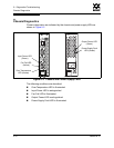
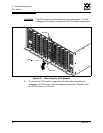
The SFP transceivers can be removed and replaced while the switch is operating
without damaging the switch or the transceiver. However, transmission on the
affected port will be interrupted until the transceiver is installed and reconnected.
To remove a transceiver, gently press the transceiver into the port to release the
tension, then pull on the release tab or lever and remove the transceiver. Different
transceiver manufacturers have different release mechanisms. Consult the
documentation for your transceiver.
To install, insert the transceiver into the port and gently press until it snaps in
place. The SFP transceiver will fit only one way. If the SFP does not install under
gentle pressure, flip it over and try again.
Table 6-1. Marginal Operating Configurations
This number of I/O
blades . . .
. . .with this number of
power supply modules
. . .
. . .requires this
number of fans.
1–4 1 2
5–8 2 2
5–8 1 3