


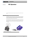
Normal and Fault Condition LED Messages
104 AX2550 Motor Controller User’s Manual Version 1.9b. June 1, 2007
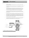
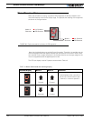
Motor Direction Status
When the controller is running, two pairs of LED segments are directly related to com-
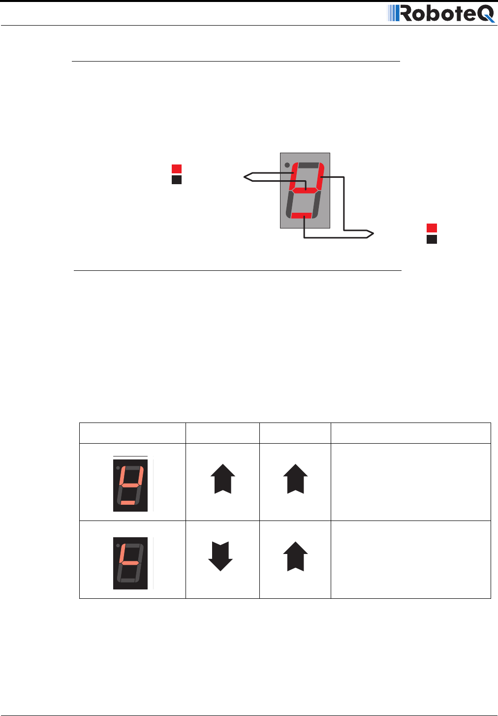
mand informations to the Power Output stage. The position and meaning of the segments
are shown in the figure below.
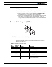
Note that the display does not provide Power information. Therefore it is possible that the
motor be stopped while the display indicates that the direction is forward. In such a situa-
tion controller is set to apply the power in the forward direction to the output stage but the
motor is stopped because the applied power is zero.
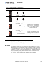
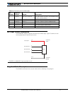
The LED can display a total of 5 patterns summarized in Table 18.
TABLE 18. Motor Commands and resulting display
Possible Display Motor 1 Motor 2 Comment
Forward Forward
Is also displayed when controller is
active with a 0 command on each
channel (i.e. motors at speed 0)
Reversed Forward
Motor 1
Direction
Lit: Forward
Off: Reverse
Motor 2
Direction
Lit: Forward
Off: Reverse
FIGURE 65. Each command bit is wired to 2 LED segments