


AX2550 Quick Start
16 AX2550 Motor Controller User’s Manual Version 1.9b. June 1, 2007
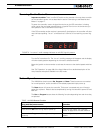
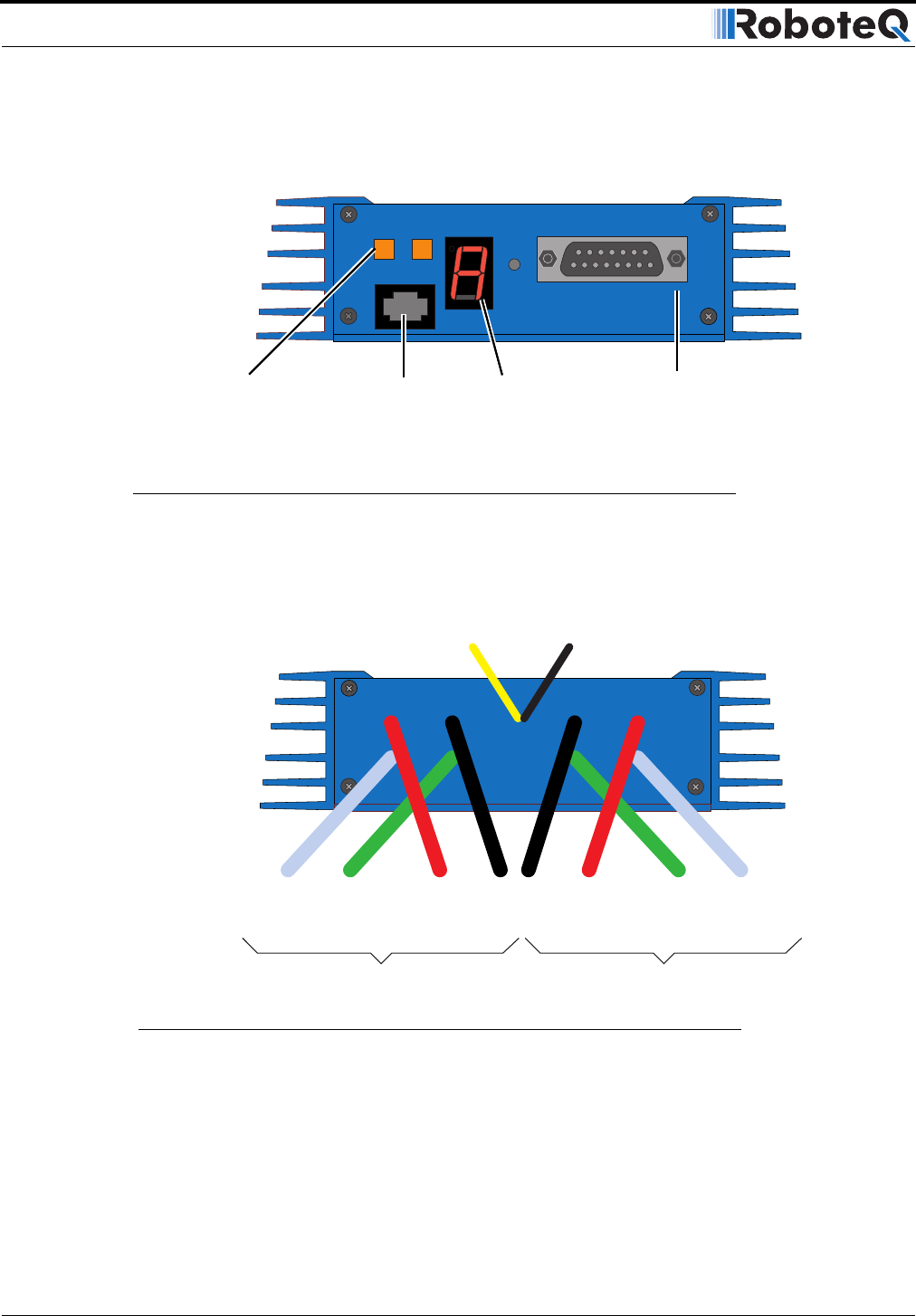
The front side (shown in Figure 1) contains the buttons and display needed to operate and
monitor the controller. The 15-pin connector provides the connection to the R/C radio, joy-
stick or microcomputer, as well as connections to optional switches and sensors.
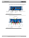
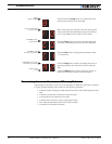
At the back of the controller (shown in the figure below) are located all the wires that must
be connected to the batteries and the motors.
Program Set
Reset
Connector to Receiver/Controls
and sensors
Operating Status
and Program LED
Display
Controller Configu-
ration buttons
FIGURE 1. Front Controller Layout
Connector to
Optical Encoders
(AX2850 only)
Controller Power
Ground (-)
Black
(top)
Power Control
Yellow
Motor 2
12 to 40V (+)
Red
Ground (-)
Black
Motor(+)
Yellow or
White
Motor (-)
Green
Motor 1
12 to 40V (+)
Red
Motor (-)
Green
Motor (+)
White
FIGURE 2. Rear Controller Layout