


166 AX2550 Motor Controller User’s Manual Version 1.9b. June 1, 2007
Controller is on, Radio is turned Off (or Radio On with RC ch3 Off)
• Relay deactivates. RS232 is now connected to shared input.
• String of Carriage Returns now received by controller.
• Computer looks for OK prompt to detect that the RS232 mode is now active.
Note: Wait 5 seconds for the capacitor to discharge before attempting to switch to RC
mode if doing this repeatedly. Controller will not reset otherwise.
Analog and R/C Modes Data Logging String Format
When the controller is configured in R/C or Analog mode, it will automatically and continu-
ously send a string of ASCII characters on the RS232 output.
This feature makes it possible to log the controller’s internal parameters while it is used in
the actual application. The data may be captured using a PC connected via an RS232 cable
or wireless modem or into a PDA installed in the actual robot. Details on how to wire the
DB15 connector is described on page 122 for the R/C mode and on page 129 for the Ana-
log mode.
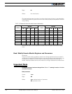
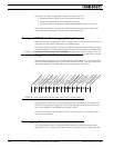
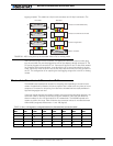
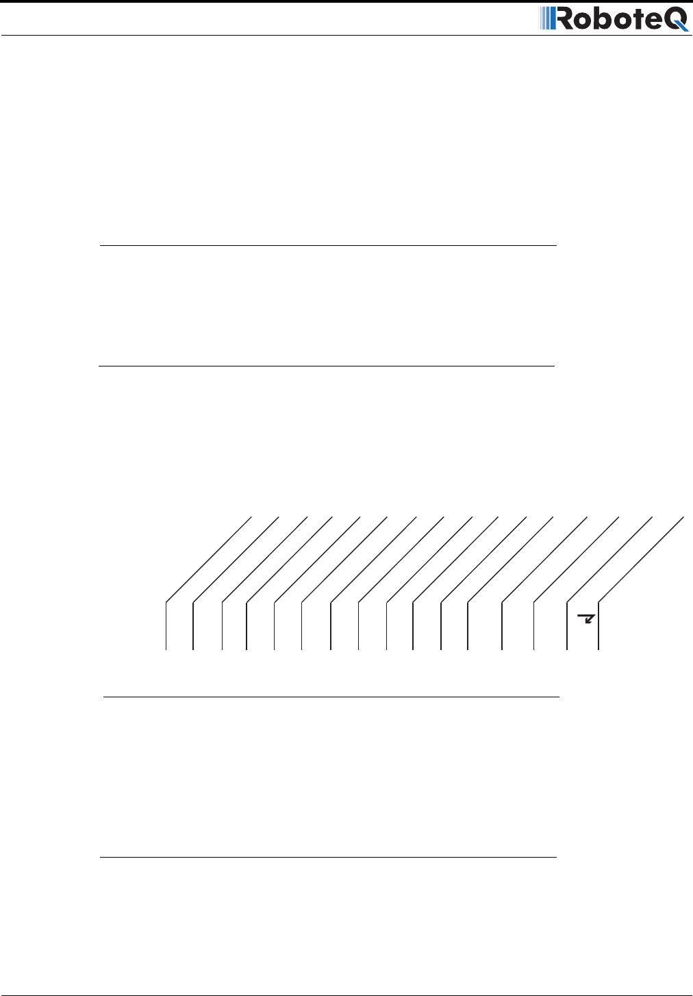
This string is composed of a start character delimiter, followed by 12 or 13 two-digit Hexa-
decimal numbers representing 12 or 13 internal parameter values, and ending with a Car-
riage Return character. The figure below shows the structure of this string.
The hexadecimal values and format for each parameter is the same as the response to
RS232 queries described in page 138. The Encoder Speed/Position parameter is output
only on the AX2850 or the AX2550 with Encoder module.
Characters are sent by the controller at the rate of one every 8ms. A complete string is
sent in 213ms or 224ms.
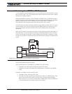
Data Logging Cables
The wring diagrams shown in the figures below describe an easy-to-assemble cable
assembly for use to create insertion points where to connect the PC for debug and data
: 00 11 22 33 44 55 66 77 88 99 AA BB CC
Start Delimiter
End Delimiter
Command 1
Command 2
Output Power 1
Output Power 2
Analog In 1
Analog In 2
Amps 1
Amps 2
Temperature 1
Temperature 2
Main Batt Volts
Internal Volts
Encoder Spd/Pos
FIGURE 94. ASCII string sent by the controller while in R/C or Analog mode
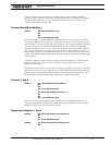
FIGURE 1. Pin locations on the controller’s 15-pin connector