


Closed Loop Position Mode
88 AX2550 Motor Controller User’s Manual Version 1.9b. June 1, 2007
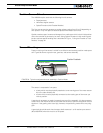
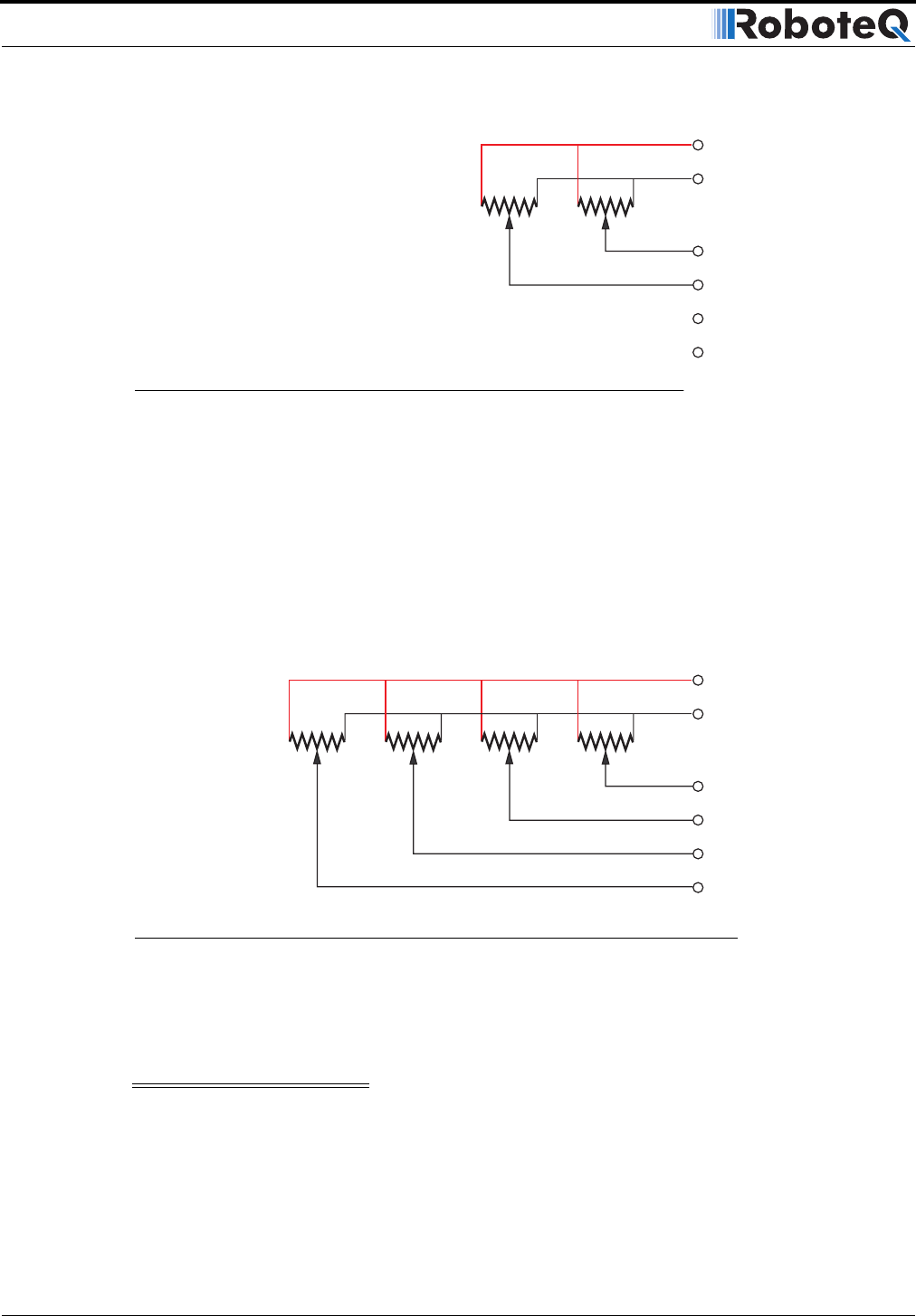
Feedback Potentiometer wiring in Analog Mode
When the controller is configured in Analog mode, the analog inputs 1 and 2 are used for
commands while the analog inputs 3 and 4 are used for feedback. Analog inputs 3 and 4
have different characteristics than inputs 1 and 2, and so require a lower resistance poten-
tiometer in order to guarantee accuracy
Note that the analog inputs 3 and 4 are only available on the AX2550 with PCB revision 6.1
or above. The PCB revision can be found on the sticker affixed at the bottom of the case.
Roborun will detect the new hardware revision and display Rev B on the screen.
Analog inputs 3 and 4 have different characteristics than inputs 1 and 2, and so require a
lower resistance potentiometer in order to guarantee accuracy.
Important Notice
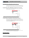
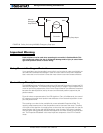
This wiring is also the one to use when the controller is in Analog mode but switched to
RS232 after reset using the method discussed in “Entering RS232 from R/C or Analog
mode” on page 136
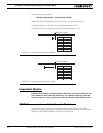
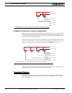
10 Ana2
14 +5V
5 Ground
11 Ana1
8 Ana4*
12 Ana3*
Feedback 1
Feedback 2
2k - 10k 2k - 10k
FIGURE 55. Pot wiring for RS232 or RC Command and Analog Feedback
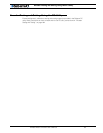
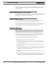
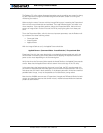
10 Ana2
14 +5V
5 Ground
Feedback 1
Command 1
Command 2
Feedback 2
11 Ana1
8 Ana4*
2k 2k 2k - 10k 2k - 10k
12 Ana3*
FIGURE 56. Pot wiring for Analog Command and Analog Feedback