


AX2550 Motor Controller User’s Manual 27
Technical features
• Tachometer inputs for closed loop speed control
• Potentiometer input for position (servo mode)
• Motor temperature sensor inputs
• External voltage sensors
• User defined purpose (RS232 mode only)
• 2 Extra analog inputs (on RevB hardware). Used as:
• Potentiometer input for position while in analog command mode
• User defined purpose (RS232 mode only)
• One Switch input configurable as
• Emergency stop command
• Reversing commands when running vehicle inverted
• General purpose digital input
• One general purpose 24V, 2A output for accessories
• Up to 2 general purpose digital inputs
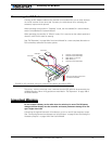
Optical Encoder Inputs (AX2850 only)
• Inputs for two Quadrature Optical Encoders
• up to 250khz Encoder frequency per channel
• two 32-bit up-down counters
• Inputs may be shared with four optional limit switches per channel
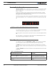
Internal Sensors
• Voltage sensor for monitoring the main 12 to 40V battery system operation
• Voltage monitoring of internal 12V
• Temperature sensors on the heat sink of each power output stage
• Sensor information readable via RS232 port
Low Power Consumption
• On board DC/DC converter for single 12 to 40V battery system operation
• Optional backup power input for powering safely the controller if the motor batteries
are discharged
• Max 200mA at 12V or 100mA at 24V idle current consumption
• Power Control wire for turning On or Off the controller from external microcomputer
or switch
• No power consumed by output stage when motors are stopped
• Regulated 5V output for powering R/C radio. Eliminates the need for separate R/C
battery
High Efficiency Motor Power Outputs
• Two independent power output stages
• Optional Single Channel operation at double the current
• Dual H bridge for full forward/reverse operation
• Ultra-efficient 2.5mOhm (1.25mOhm on HE version) ON resistance (RDSon) MOS-
FET transistors
• Synchronous Rectification H Bridge