


Installing, Connecting and Using the Encoder Mod-
78 AX2550 Motor Controller User’s Manual Version 1.9b. June 1, 2007
Important Warning
When a limit switch is activated, the encoder signal that is shared with the switch is
no longer visible by the encoder module, and pulse counting and speed measure-
ment stops.
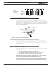
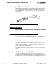
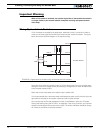
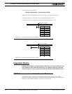
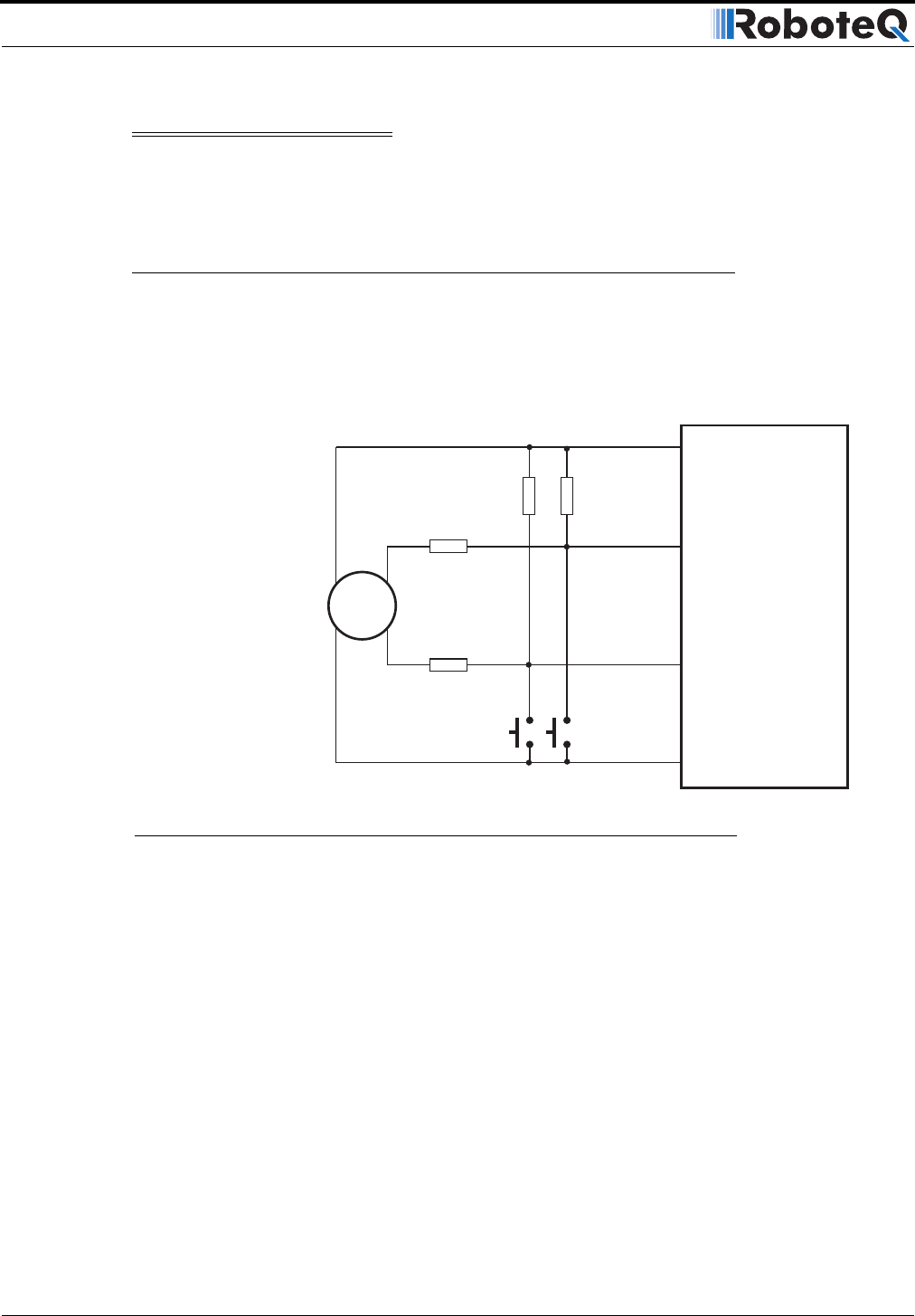
Wiring Optional Limit Switches
If limit switches are needed by the application, additional circuitry is required in order to
create a multi-level signal that shares the encoder and the switch information. The figure
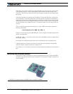
below shows the electrical diagram of the required wiring.
Using this circuit when the switch is open, a 0V (low-level) output from the encoder goes
through a 1k and 4.7k voltage divider, thus creating a voltage that will never be below 0.8V
at the encoder module’s input.
When the switch is activated, the module’s input is pulled to 0V.
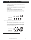
It is recommended that a voltmeter and/or oscilloscope be used to verify that the right volt-
age levels are created as the encoder rotates and the switches activate.
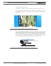
You may also use the Encoder setup/test function in the Roborun utility (see “Encoder
Testing and Setting Using the PC Utility” on page 83). If the wiring is correct, the counters
should increment/decrement as the motor rotate. The switch indicators should be always
off unless the switches are actually activated.
Encoder
SW1
SW2
Encoder Module
1kOhm
GND
5V Out
Ch A In
Ch A
Ch B
Ch B In
5V
GND
1kOhm
4.7kOhm
4.7kOhm
FIGURE 50. Signals seen by encoder using multi-levels and limit switches