


Connecting Sensors and Actuators to Input/Outputs
58 AX2550 Motor Controller User’s Manual Version 1.9b. June 1, 2007
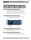
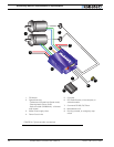
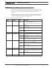
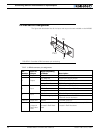
I/O List and Pin Assignment
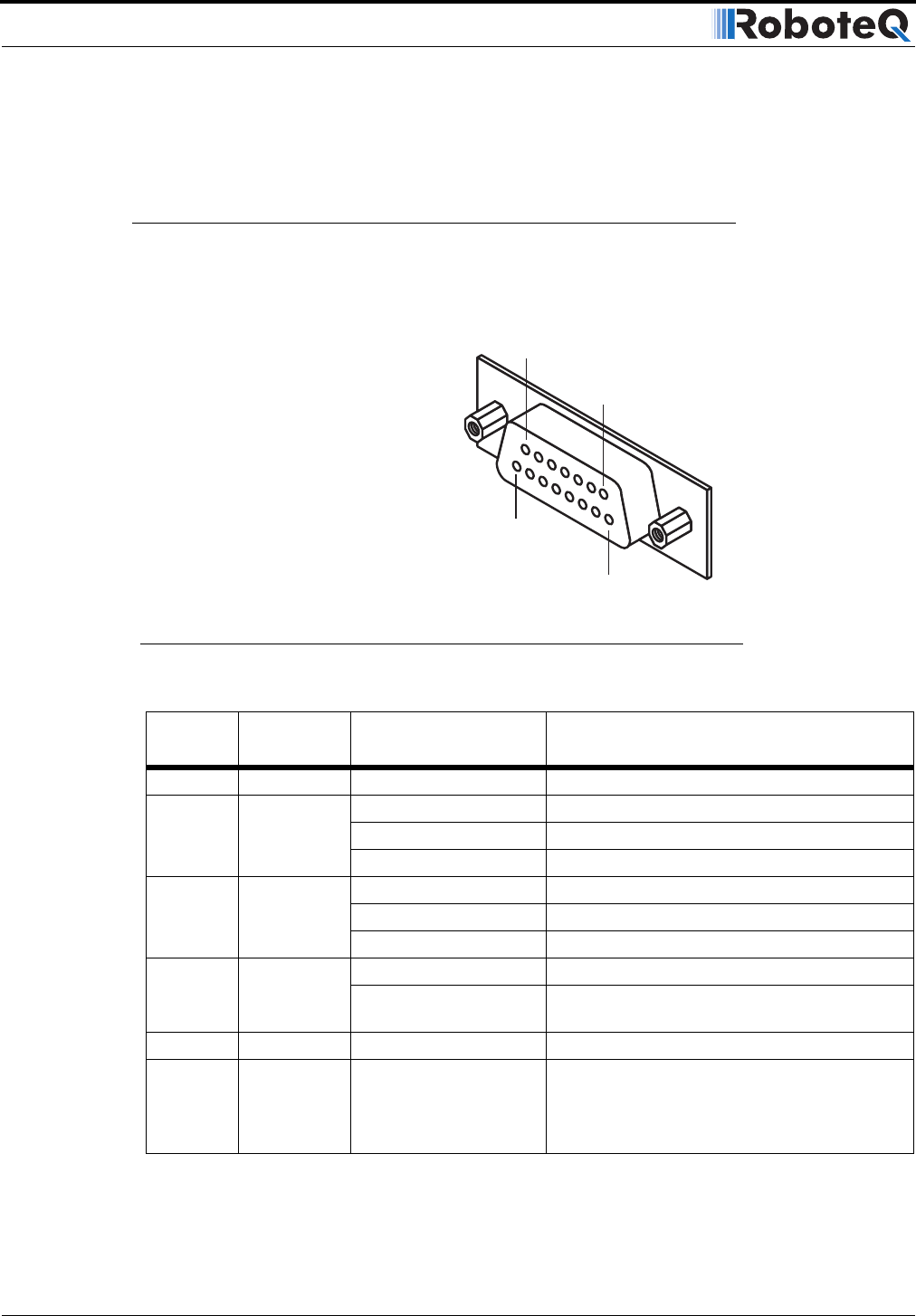
The figure and table below lists all the inputs and outputs that are available on the AX2550.
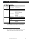
TABLE 10. DB15 connector pin assignment
Pin
Number
Input or
Output
Signal depending
on Mode Description
1 and 9 Output Output C 2A Accessory Output C
2Output
R/C: Data Out RS232 Data Logging Output
RS232: Data Out RS232 Data Out
Analog: Data Out RS232 Data Logging Output
3 Input
R/C: Ch 1 R/C radio Channel 1 pulses
RS232: Data In RS232 Data In (from PC/MCU)
Analog: Unused Unused
4 Input
R/C: Ch 2 R/C radio Channel 2 pulses
RS232/Analog: Input F Digital Input F readable RS232 mode
Dead man switch activation
5 and 13 Power Out Ground Controller ground (-)
6 GND In
Unused in
RevB Hard-
ware
Ground
Unused in RevB Hard-
ware
Optocoupler GND Input, Connect to pin 5**
Unused in RevB Hardware
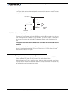
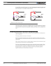
Pin1
8
15
9
FIGURE 27. Controller’s DB15 connector pin numbering