


AX2550 Motor Controller User’s Manual 77
Voltage Levels, Thresholds and Limit Switches
On the 2850 family of controllers, the threshold voltage may be changed under software
control to any value between 0 and 5V in order to meet unusual encoder specifications. By
default, the threshold level is 2.5V.
Another set of comparators on the same input signals detects pulses that are above and
below a fixed 0.5V threshold. Using a special circuitry for creating multi-level signaling (see
next section below), the output of these comparators serves to detect the status of
optional limit switches.
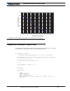
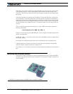
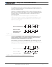
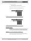
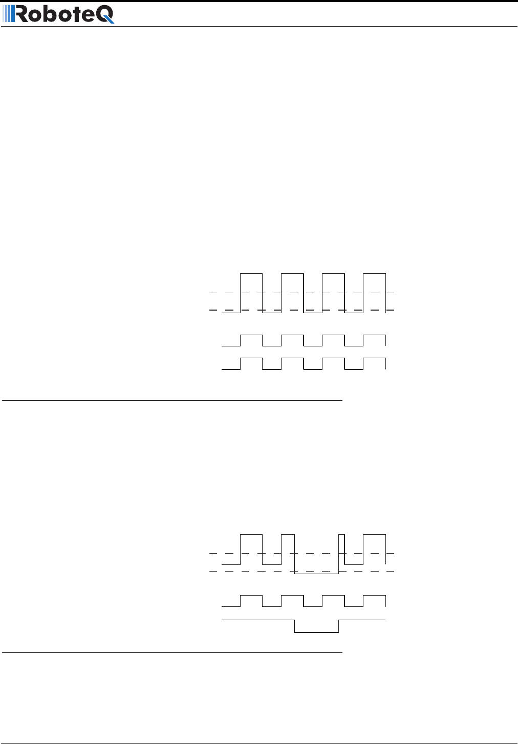
Figure 49 and Figure 48 show the conditioned signals as seen by the encoder.
In Figure 49, the encoders are connected directly to the Channel A and B inputs. In this
case, it will cause a Switch Detection condition because the encoder’s 0 level is below
0.5V, which should be ignored.
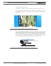
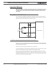
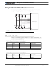
In Figure 48, the encoder and switches are wired to the encoder module using a set of
resistors designed to create a multi-level signal combining both pieces of information.
Details on the necessary wiring is provided in the next section.
Since the encoder output signal is “shifted-up” by a few volts, it always stays above the
Limit Switch comparator’s threshold, and no Switch Detection condition is generated.
However, since the limit switches connect to ground when On, the level will dip below the
0.5V and generate a Switch Detection condition.
2.5V
0.5V
Signal on Channel A or B
Quadrature Signal
Switch Detect Signal
(Not meaningful)
FIGURE 48. Signals seen by encoder using direct connection and no limit switches
2.5V
0.5V
Signal on Channel A or B
Quadrature Signal
Switch Detect Signal
FIGURE 49. Signals seen by encoder using multi-levels and limit switches