General Operation
50 AX2550 Motor Controller User’s Manual Version 1.9b. June 1, 2007
is found on all R/C transmitters, and which is actually an offset correction, the Left/Right
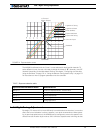
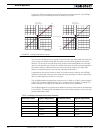
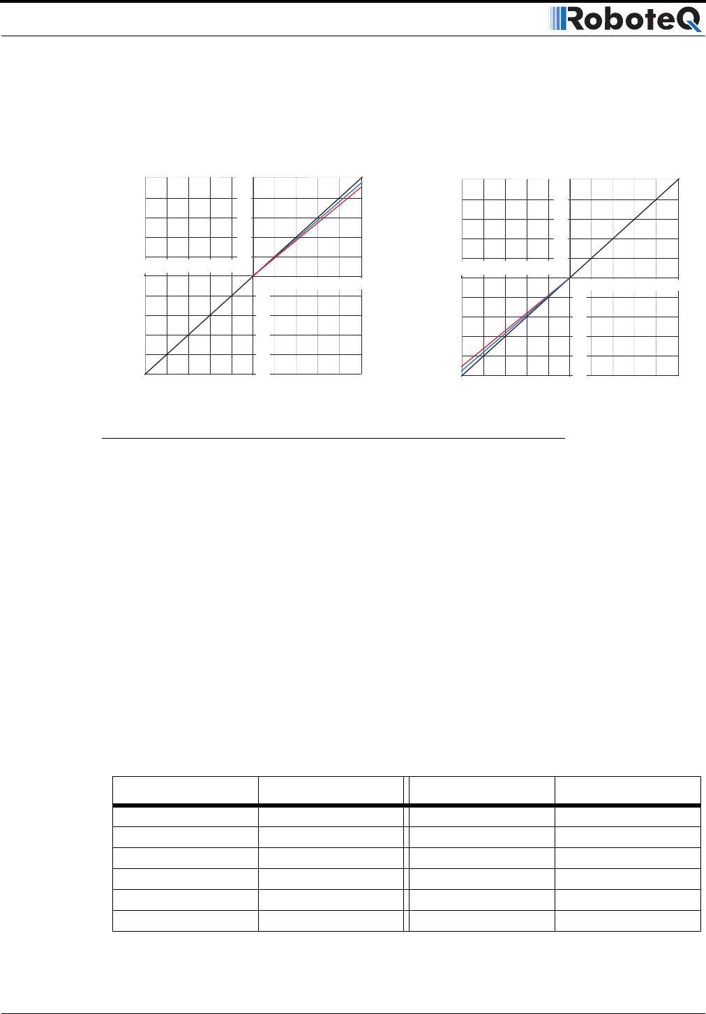
Adjustment is a true multiplication factor as shown in Figure 22
The curves on the left show how a given forward direction command value will cause the
motor to spin 3 or 5.25% slower than the same command value applied in the reverse
direction. The curves on the right show how the same command applied to the forward
direction will case the motor to spin 3 to 5.25% faster than the same command applied in
the reverse direction. Note that since the motors cannot be made to spin faster than
100%, the reverse direction is the one that is actually slowed down.
In applications where two motors are used in a mixed mode for steering, the Left/Right
Adjustment parameter may be used to make the robot go straight in case of a natural ten-
dency to steer slightly to the left or to the right.
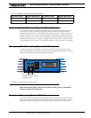
The Left/Right adjustment parameter can be set from -5.25% to +5.25% in seven steps of
0.75%. See “Programmable Parameters List” on page 174 and “Loading, Changing Con-
troller Parameters” on page 181 for details on how to adjust this parameter.
The Left/Right adjustment is performed in addition to the other command curves described
in this section. This adjustment is disabled when the controller operates in any of the sup-
ported closed loop modes.
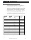
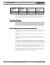
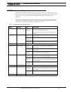
TABLE 8. Left/Right Adjustment Parameter selection
Parameter Value Speed Adjustment Parameter Value Speed Adjustment
7 None (default)
0 -5.25% 8 0.75%
1-4.5%91.5%
2 -3.75% 10 2.25%
3 -3% 11 3%
4 -2.25% 12 3.75%
20
40
60
80
100
0
20
40
60
80
100
- 20
- 40
- 60
- 80
- 100
20
40
60
80
100
% Forward
(Motor Output)
0%
3%
5.25%
% Reverse
% Command Input
20
40
60
80
100
0
20
40
60
80
100
- 20
- 40
- 60
- 80
- 100
20
40
60
80
100
% Forward
(Motor Output)
% Forward
(Motor Output)
0%
-3%
-5.25%
% Reverse
FIGURE 22. Left Right adjustment curves


