


Analog Control and Operation
128 AX2550 Motor Controller User’s Manual Version 1.9b. June 1, 2007
Important Notice
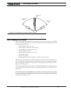
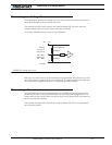
Some analog joysticks do not cause the potentiometer to reach either extreme. This
may cause the analog voltage range to be above 0V and below 5V when the stick is
moved to the extreme, and therefore the controller will not be able to deliver full for-
ward or reverse power.
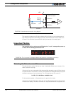
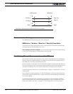
Power-On Safety
When powering on the controller, power will not be applied to the motors until both the
Channel 1 and Channel 2 potentiometers have been centered to their middle position (2.5V
on each input). This is to prevent the robot or vehicle from moving, in case the joystick was
in an active position at the moment the controller was turned on. The “no ctrl” message
will scroll on the LED display while the controller is disabled.
Under Voltage Safety
If the controller is powered through the Power Control input and the motor battery voltage
drops below 5V, the controller will be disabled until the analog commands are centered to
the midpoint (2.5V on each input).
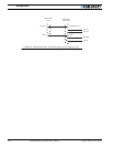
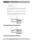
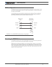
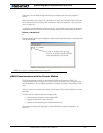
Data Logging in Analog Mode
While in Analog Mode, the AX2550 will continuously send a string of characters on the
RS232 output line. This string will contain 12 or 13 two-digits hexadecimal number repre-
senting the following operating parameters.
• Captured Analog Command 1 and 2
• Power Applied to Controller’s output stage
• Raw analog command values
• Amps on channel 1 and 2
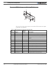
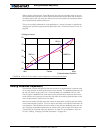
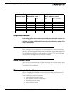
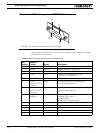
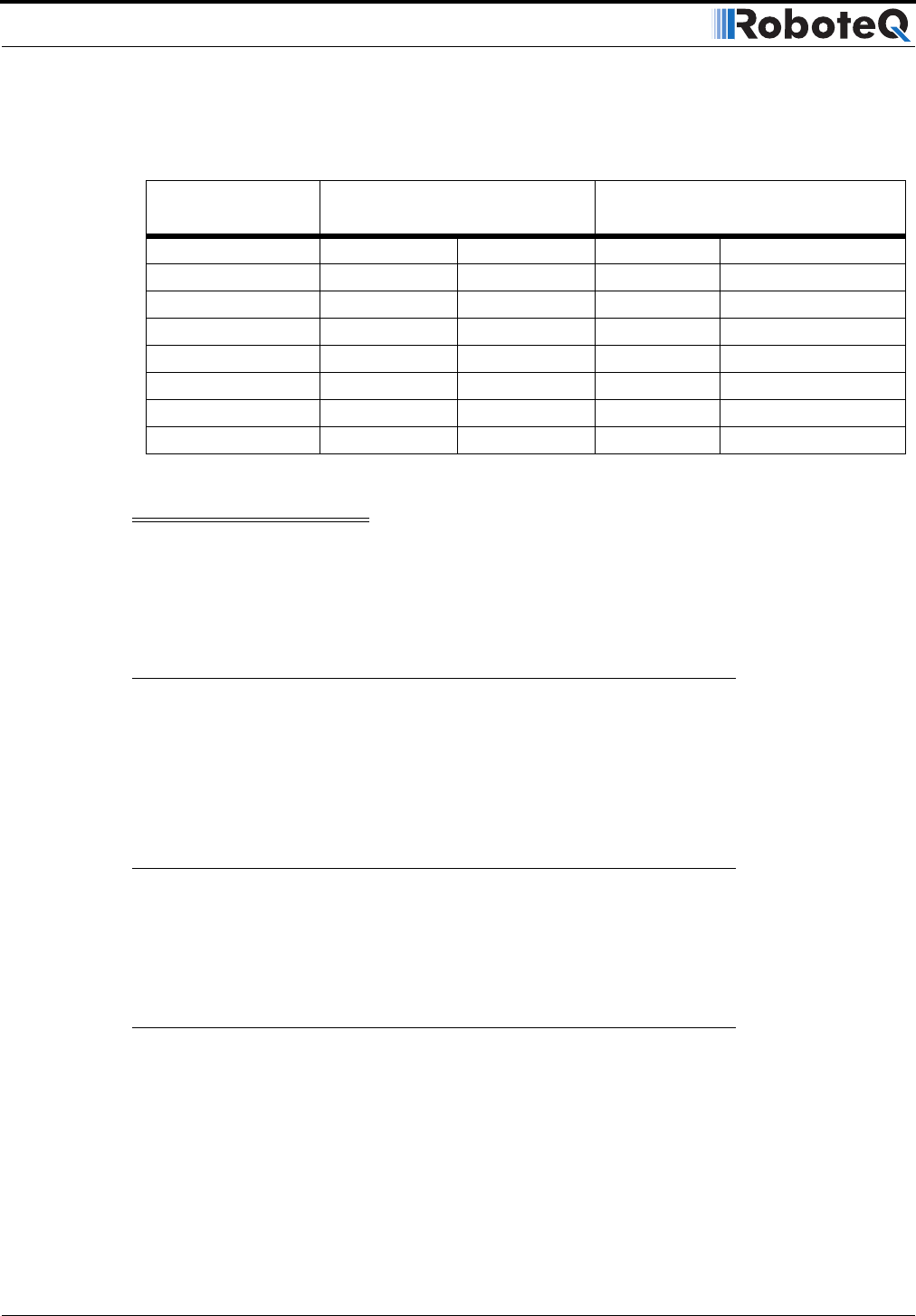
TABLE 22. Analog deadband parameters and their effects
Parameter Value
Pot. Position resulting in
Motor Power at 0%
Pot. Position resulting in
Motor Power at -/+100%
0 0% 2.5V 94% 0.15V and 4.85V
1 0% to 2.4% 2.44V to 2.56V 96% 0.10V and 4.90V
2 0% to 4.7% 2.38V to 2.62V 93% 0.18V and 4.83V
3 (default) 0% to 7.1% 2.32V to 2.68V 95% 0.13V to 4.88V
4 0% to 9.4% 2.27V to 2.74 93% 0.18V and 4.83V
5 0% to 11.8% 2.21V to 2.80V 95% 0.13V to 4.88V
6 0% to 14.2% 2.15V to 2.86V 94% 0.15V and 4.85V
7 0% to 16.5% 2.09V to 2.91V 96% 0.10V and 4.90V