AX2550 Motor Controller User’s Manual 185
Encoder Setting and Testing
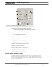
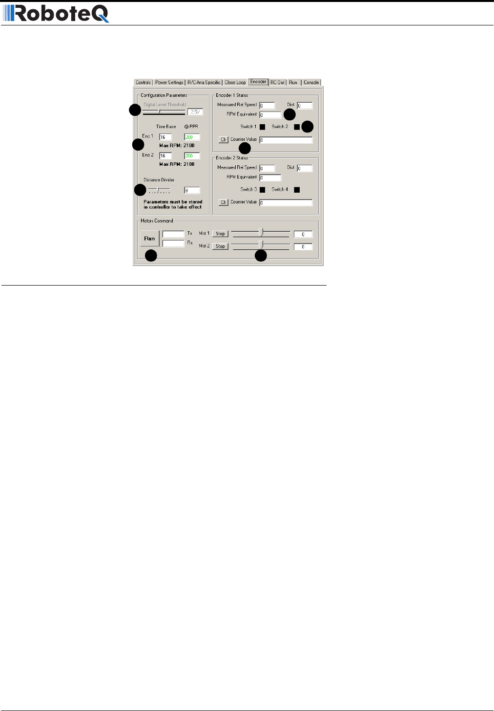
With this utility, the following actions can be accomplished:
• Set and program the Encoder module’s parameters in EEPROM
• Activate the motors in each direction at variable speed
• View the measured encoder counts
• View the measured encoder speed
• View the status of the Limit Switches
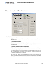
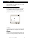
The screen is composed of the following buttons and displays:
1- Setting of the Encoder’s threshold level
2- Setting of the Time Base for speed computation
3- Setting Divider for computing relative distance
4- Measure and display speed and relative distance
5- Measure and display counter values
6- Detect and display optional limit switch status
7- Start/Stop communication with controller
8- Set motor speed and direction for testing
Encoder Module Parameters Setting
The Encoder module has four programmable parameters: Two Time Bases (one for each
encoder), a Divider for computing relative distance, and the voltage threshold for discern-
ing a 0 or 1 level at the encoder’s output. In the case of the AX2550, the threshold is fixed
at 2.5V and cannot be changed.
FIGURE 104. Encoder setup and test screen on Roborun
1
2
3
7
5
4
6
7


