


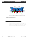
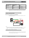
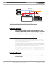
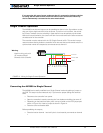
Connecting Power and Motors to the Controller
30 AX2550 Motor Controller User’s Manual Version 1.9b. June 1, 2007
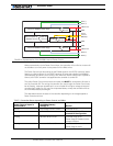
Controller Power
The AX2550 uses a flexible power supply scheme that is best described in Figure 9. In this
diagram, it can be seen that the power for the Controller’s microcomputer is separate from
this of the motor drivers. The microcomputer circuit is connected to a DC/DC converter
which takes power from either the Power Control wire or the VMot input. The diode circuit
is designed to automatically select one power source over the other, letting through the
source that is higher than the other.
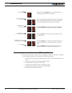
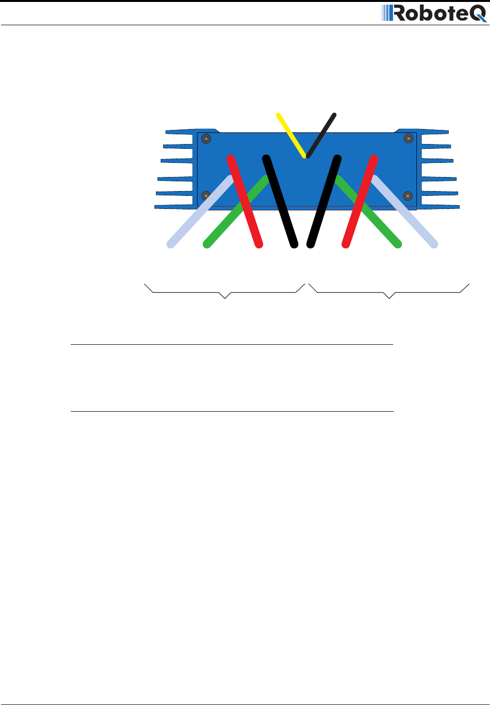
Controller Power
Ground (-)
Black
(top)
Power Control
Ye l l ow
Motor 2
12 to 40V (+)
Red
Ground (-)
Black
Motor(+)
Yellow or
White
Motor (-)
Green
Motor 1
12 to 40V (+)
Red
Motor (-)
Green
Motor (+)
White
FIGURE 8. Controller rear plate and power wiring