


Closed Loop Speed Mode
98 AX2550 Motor Controller User’s Manual Version 1.9b. June 1, 2007
Using Optical Encoder for Speed Feedback (AX2850 only)
Digital Optical Encoders may be used to capture accurate motor speed. This capability is
only available on controllers fitted with the optional encoder module.
Detailed information on how to install and wire optical encoders is provided at “Installing,
Connecting and Using the Encoder Module” on page 71.
If using optical encoders, omit the Analog Tachometer discussion in this section and
resume reading from “Control Loop Description” on page 100. Optical Encoders require
special handling. See “Installing, Connecting and Using the Encoder Module” on page 71
for a detailed discussion.
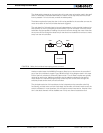
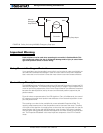
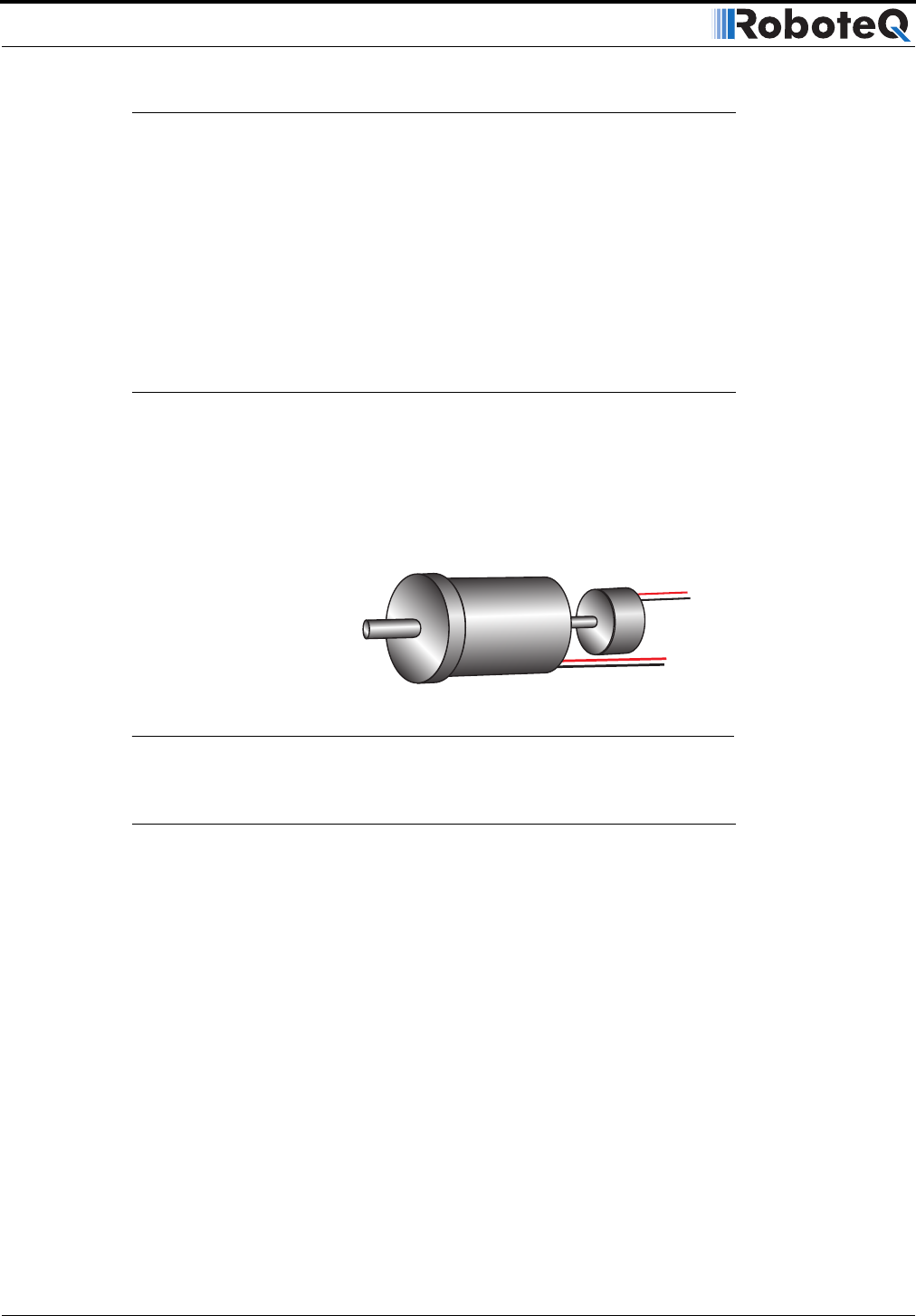
Tachometer or Encoder Mounting
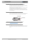
Proper mounting of the speed sensor is critical for an effective and accurate speed mode
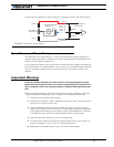
operation. Figure 62 shows a typical motor and tachometer or encoder assembly.
Tachometer wiring
The tachometer must be wired so that it creates a voltage at the controller’s analog input
that is proportional to rotation speed: 0V at full reverse, +5V at full forward, and 0 when
stopped.
P iti F db k
FIGURE 62. Motor and speed sensor assembly needed for Close Loop Speed mode
Speed feedbackSpeed feedback
Analog Tachometer
or Optical Encoder