


AX2550 Motor Controller User’s Manual 111
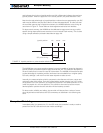
R/C Input Circuit Description
R/C Input Circuit Description
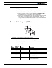
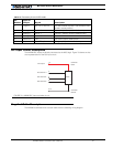
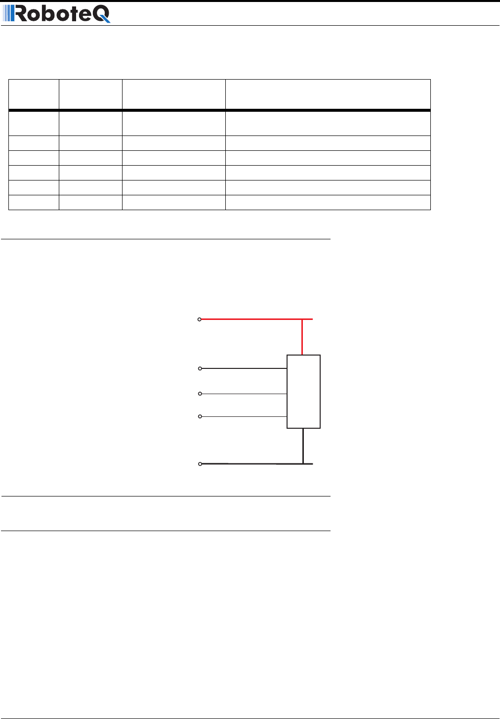
The AX2550 R/C inputs are directly connected to the MCU logic. Figure 70 shows an elec-
trical representation of the R/C input circuit.
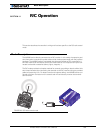
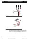
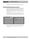
Supplied Cable Description
The AX2550 is delivered with a custom cable with the following wiring diagram:
8 Digital In R/C: Ch 3 / Ana In 4 R/C radio Channel 3 pulses - (Not available when
encoder module present)
10 Analog in Ana in 2 Channel 2 speed or position feedback input
11 Analog in Ana in 1 Channel 1 speed or position feedback input
12 Analog in Ana in 3 Unused
14 Power Out +5V +5V Power Output (100mA max.)
15 Input Input EStop/Inv Emergency Stop or Invert Switch input
TABLE 19. Connector pin-out in R/C mode
Pin
Number
Input or
Output Signal Description
14
3
8
5-13
4
MCU
R/C Channel 1
R/C Channel 2
R/C Channel 3
Controller
Ground
Controller
Power
+5V Output
FIGURE 70. AX2550 R/C Input equivalent circuit