


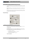

Configuring the Controller using the Switches
176 AX2550 Motor Controller User’s Manual Version 1.9b. June 1, 2007
*The coast function is not implemented in this revision of the software. The controller will
only operate in brake mode.
** Values are in hexadecimal numbers where the decimal values 10, 11, 12... 15 are repre-
sented with the letters A, B, C... F.
*** Deadband percent values shown are for R/C mode. For analog deadband values, see
page 127.
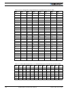
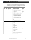
5 U Input switch function 0 = causes emergency stop
1 = invert commands switch
(2) = no action (default)
page 51
page 52
6 b Brake/Coast Not implemented
7 d R/C Joystick Dead-
band
Analog Input Dead-
band
0 = no deadband ***
1 = 8%
(2) = 16% (default)
3 = 24%
4 = 32%
5 = 40%
6 = 46%
7 = 54%
page 117
page 127
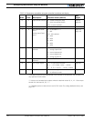
8 E Exponentiation on
channel 1
(0) = Linear (no exponentiation - default)
1 = strong exponential
2 = normal exponential
3 = normal logarithmic
4 = strong logarithmic
page 118
9 F Exponentiation on
channel 2
Same as E, above
10 L Left / Right Adjust (7) = no adjustment (default)
0, 1, ..., 6 = -5.25%, -4.5%, ...,-0.75%
8, ..., D, E** = +0.75, ..., +4.5%, +5.25%
page 49
11 J Joystick calibration - = not calibrating
o = in calibration mode
page 118
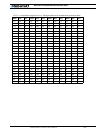
TABLE 35. Parameters accessible using the controller’s switches and display
Order Letter Description Possible Values (default)
See
pages