AX2550 Motor Controller User’s Manual 91
Encoder Error Detection and Protection
9. If the motor turns in the direction in which the sensor was moved, the polarity is
correct. The sensor axle may be tighten to the motor assembly.
10. If the motor turns in the direction away from the sensor, then the polarity is
reversed. The wire polarity on the motors should be exchanged. If using a potenti-
ometer as sensor, the GND and +5V wires on the potentiometer may be swapped
instead. If using an Optical Encoder, ChA and ChB outputs can be swapped.
11. Move the sensor back to the center point to stop the motor. Cut the power if con-
trol is lost.
12. If the polarity was wrong, invert it and repeat steps 8 to 11.
13. Tighten the sensor.
Important Safety Warning
Never apply a command that is lower than the sensor’s minimum output value or
higher than the sensor’s maximum output value as the motor would turn forever try-
ing to reach a position it cannot. For example, if the max position of a potentiometer
is 4.5V, which is a position value of 114, a destination command of 115 cannot be
reached and the motor will not stop.
Encoder Error Detection and Protection
The AX2550 contains an Encoder detection and protection mechanism that will cause the
controller to halt if no motion is detected on either Encoder while a power level of 25% or
higher is applied to the motor. If such an error occurs, the controller will halt permanently
until its power is cycled or it is reset. An Encoder error is one of the conditions that is sig-
naled by the LED rapidly flashing an “8” character (see “Permanent Faults” on page 106).
Adding Safety Limit Switches
The Position mode depends on the position sensor providing accurate position information.
If the potentiometer is damaged or one of its wire is cut, the motors may spin continuously
in an attempt to reach a fictitious position. In many applications, this may lead to serious
mechanical damage.
To limit the risk of such breakage, it is recommended to add limit switches that will cause
the motors to stop if unsafe positions have been reached independent of the potentiome-
ter reading.
If the controller is equipped with and Encoder module, the simplest solution is to imple-
ment limit switches as shown in “Wiring Optional Limit Switches” on page 78. This wiring
can be used whether or not Encoders are used for feedback.
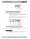
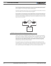
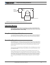
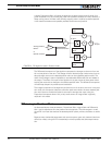
If no Encoder module is present, an alternate method is shown in Figure 59. This circuit
uses Normally Closed limit switches in series on each of the motor terminals. As the motor
reaches one of the switches, the lever is pressed, cutting the power to the motor. The
diode in parallel with the switch allows the current to flow in the reverse position so that
the motor may be restarted and moved away from that limit.


