


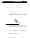
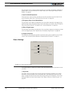
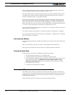
Using the Roborun Configuration Utility
182 AX2550 Motor Controller User’s Manual Version 1.9b. June 1, 2007
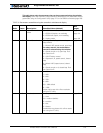
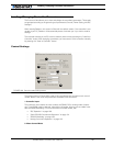
This pull down menu is used to choose whether the controller will operate in Separate or
Mixed mode. For more information on these modes, see “Selecting the Motor Control
Modes” on page 42.
3- Input Command Adjustment
These pull down menus will let you select one of five conversion curves on each of the
input command values. See “Command Control Curves” on page 48.
4- Emergency Stop or Invert Switch Select
This pull down menu allows the selection of the controller’s response to changes on the
optional switch input: Emergency Stop, Invert Commands, or no action. See “Emergency
Stop using External Switch” on page 51 and “Inverted Operation” on page 52.
5- Effect of Digital Inputs
This pull down menu allows the selection of the controller’s response to changes on either
of the two digital inputs. See “Special Use of Accessory Digital Inputs” on page 52.
6- Output C Activation
This check box will cause the controller to activate when power is applied to one or both
motors. See “Activating Brake Release or Separate Motor Excitation” on page 51.
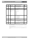
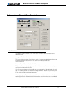
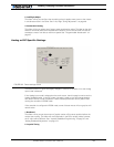
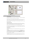
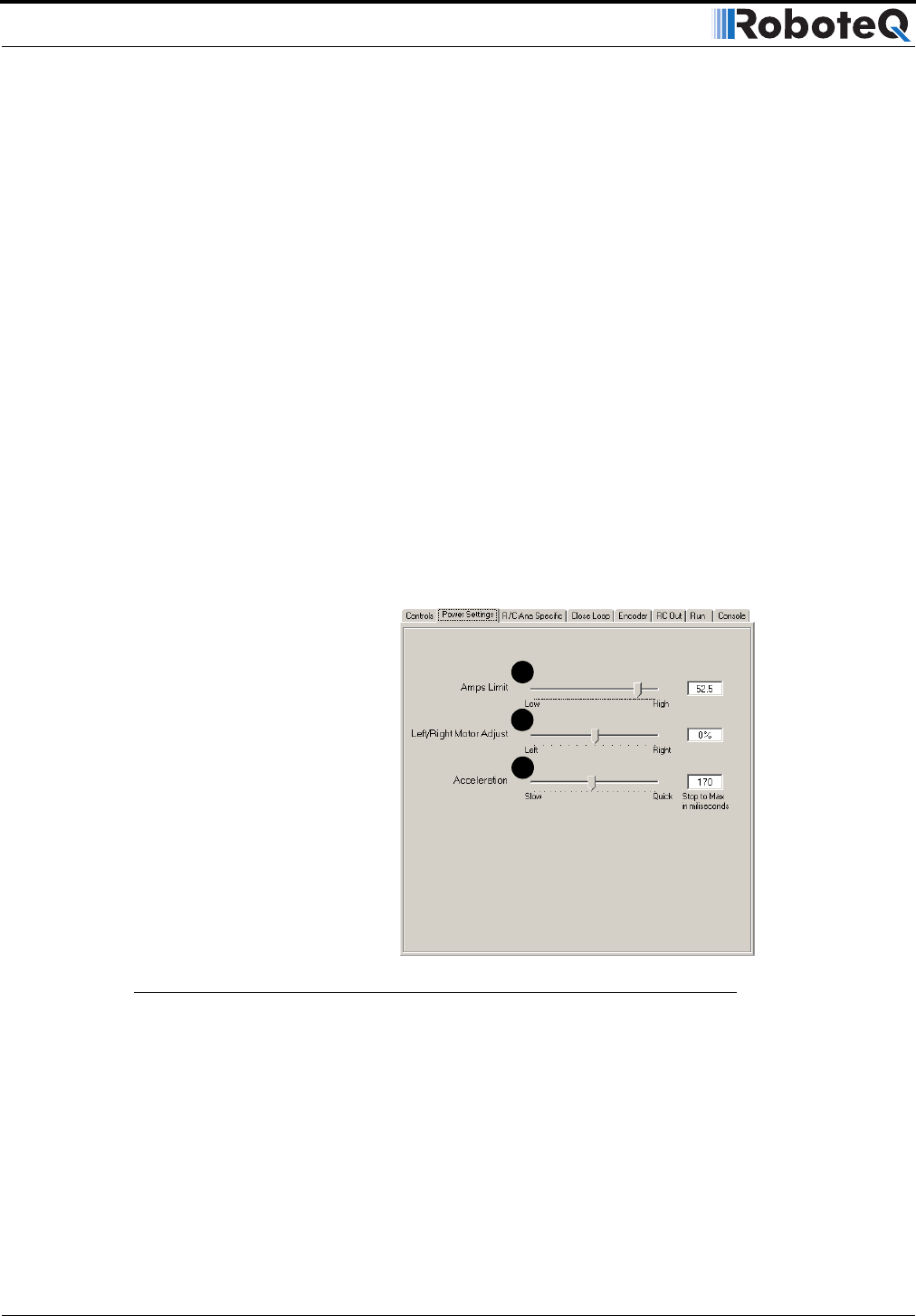
Power Settings
The screen shown in Figure 101 is used to view and change the power parameters of the
controller.
1- Amps limit
This slider will let you select the max amps that the controller will deliver to the motor
before the current limitation circuit is activated. See “User Selected Current Limit Set-
tings” on page 44. Note that this limits the current flowing from the battery. The current
flowing through the motor may be higher. See “Battery Current vs. Motor Current” on
page 45.
FIGURE 101. Power settings screen
1
2
3