


R/C Operation
120 AX2550 Motor Controller User’s Manual Version 1.9b. June 1, 2007
Notes:
If you attempt to calibrate the joysticks while the radio is off or not connected to the con-
troller, the calibration data will not change and the previously stored information will con-
tinue to be used.
If calibration is performed with only one R/C channel connected to the controller, then only
the joystick that is active will be calibrated. The other channel will keep its original settings.
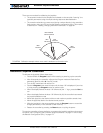
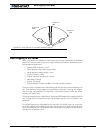
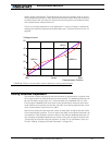
A minimum amount of travel is required between the min, max and center joystick posi-
tions. If, while calibrating, the joystick has not been moved far enough from either side of
the center position, the controller will automatically include a minimum of travel to ensure
proper and safe operation. In most cases, this creates no undesired effect to the driving
characteristics of the robot.
R/C calibration only applies to the channel 1 and channel 2 inputs. The accessory activation
channel (channel 3) is preset at the factory and cannot be changed.
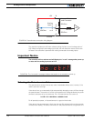
Important Notice
To ensure that only stable pulses are present, the R/C transmitter and radio must be
On before entering joystick calibration.
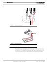
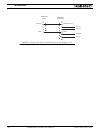
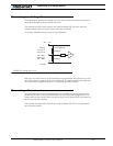
Activating the Accessory Outputs
The AX2550 has a general purpose output that may be turned on and off using a third R/C
channel on the radio.
Output C is a buffered output capable of driving a 2A device at up to 24V. Details on how to
wire this output to user accessories can be found at “Connecting Sensors and Actuators to
Input/Outputs” on page 55.
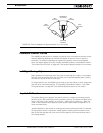
The output is activated by pushing the joystick to the maximum position. The output turns
back off when the joystick is returned to the center position.
Note: Channel 3 is not available on the controllers equipped with encoder inputs.