


AX2550 Motor Controller User’s Manual 163
Counter Read Data Format
Counter Read Data Format
When receiving a counter read query, the encoder module will output the value of its 32-bit
counter. If all 32-bit are sent, this would require 8 ASCII digits to represent the value.
A 32-bit counter can store over 2 billion counts in each direction. In practice, it will be rare
that counts will be so large than only a partial number of the counter’s bits will be signifi-
cant at any given time.
In order to create a more efficient data stream on the controller’s serial port, a simple com-
pression technique is implemented. The scheme eliminates all of the counter’s most signif-
icant bits if they are at 0 (for a positive count number) or F (for a negative count number).
For example, if the counter value is Hex 00000015, the value 15 will be returned after a
counter query.
For negative numbers, a count value of -5 (which is FFFFFFFB in hex), the response to the
query will be B.
To distinguish between positive and negative numbers, the Encoder module will insert a 0
ahead of any number string starting with a digit value higher than 7 (i.e. 8 to F) to signify
that the number is positive. For negative numbers, the Encoder module will insert an F
ahead of any number string starting with a digit value lower than 8 (i.e. 0 to 7). The table
below shows examples of this scheme as applied to various counter values.
When reading the counter value into a microcomputer, the reverse operation must take
place: any output that is less than 8 digit long must be completed with a string of 0’s if the
first digit is of value 0 to 7, or with a string of F’s if the first digit is of value 8 to F.
The resulting Hex representation of a signed 32-bit number must then be converted to
binary or decimal as required by the application.
The burden of this extra processing is more than offset by the bandwidth relief on the con-
troller’s serial port.
Encoder Testing and Setting Using the PC Utility
Extensive diagnostic, calibration, setting and testing support is provided in the Roborun PC
utility. Basic instructions on how to install and run the PC utility can be found in “Using the
Roborun Configuration Utility” on page 177
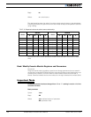
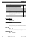
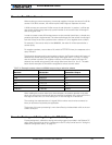
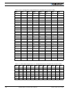
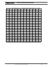
TABLE 32. Example counter values and RS232 output using a reduction scheme
Decimal 32-bit Hex Controller Output
+5 00000005 5
+250 000000FA 0FA
-6 FFFFFFFA A
-235 FFFFFF15 F15
+91,011,186 056CB872 56CB872
-7,986,091 FF862455 862455