


Analog Control and Operation
126 AX2550 Motor Controller User’s Manual Version 1.9b. June 1, 2007
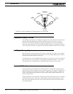
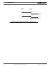
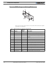
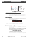
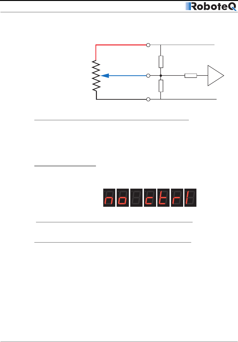
The controller includes two 47K ohm resistors pulling the input to a mid-voltage point of
2.5V. When configured in the Analog Input mode, this will cause the motors to be at the
Off state if the controller is powered with nothing connected to its analog inputs.
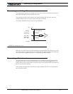
Important Notice
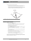
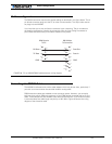
The controller will not activate and will display the “no ctrl” message after power up
or reset until the analog inputs are at 2.5V
Selecting the Potentiometer Value
The potentiometer can be of almost any value. Undesirable effects occur, however, if the
value is too low or too high.
If the value is low, an unnecessarily high and potentially damaging current will flow through
the potentiometer. The amount of current is computed as the voltage divided by the poten-
tiometer’s resistance at its two extremes. For a 1K potentiometer, the current is:
I = U/R = 5V / 1000 Ohms = 0.005A = 5mA
For all practical purposes, a 1K potentiometer is a good minimal value.
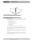
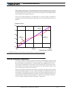
If the value of the potentiometer is high, then the two 47K resistors built into the controller
will distort the reading. The effect is minimal on a 10K potentiometer but is significant on a
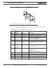
47kOhm
10kOhm
47kOhm
10kOhm
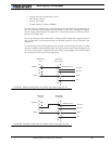
Internal Resistors
and Converter
Analog
Input 1
2
3
or 4
+5V
14
10
11
12
8
13
Ground
A/D
FIGURE 84. Potentiometer connection wiring diagram
FIGURE 85. The “no control” message indicates that joystick is not centered at power up