


AX2550 Motor Controller User’s Manual 75
Connecting the Encoder
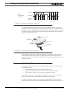
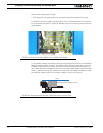
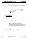
4- Slide the cover back on. Install the new face plate.
Connecting the Encoder
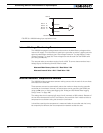
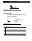
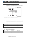
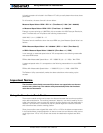
The Encoder module uses a widely available 8-pin RJ45 connector identical to those found
on all Ethernet devices. The connector provides 5V power to the encoders and has inputs
for the two quadrature signals from each encoder. Using multi-level signaling, it is also pos-
sible to share the quadrature inputs with limit switches. The figure and table below
describe the connector and its pin assignment.
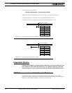
TABLE 14. Encoder Connector Pinout
Pin Name
Cable Color
(when using standard network cable)
1 Encoder 2 - Channel B. Optional Limit Switch 4 Orange/White
2 Encoder 2 - Channel A. Optional Limit Switch 3 Orange
3 Ground (same as pin 7) Green/White
4 5V Out (same as pin 8) Blue
5 Encoder 1 - Channel B. Optional Limit Switch 2 Blue/White
6 Encoder 1 - Channel A. Optional Limit Switch 1 Green
7 Ground (same as pin 3) Brown/White
8 5V Out (same as pin 4) Brown
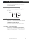
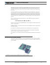
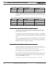
Solder wire
Encoder Module
Main Board
FIGURE 45. Solder wire for robust assembly
1
1
8
8
FIGURE 46. Encoder connector