


AX2550 Motor Controller User’s Manual 127
Analog Deadband Adjustment
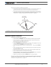
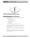
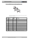
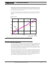
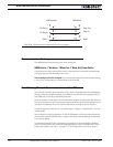
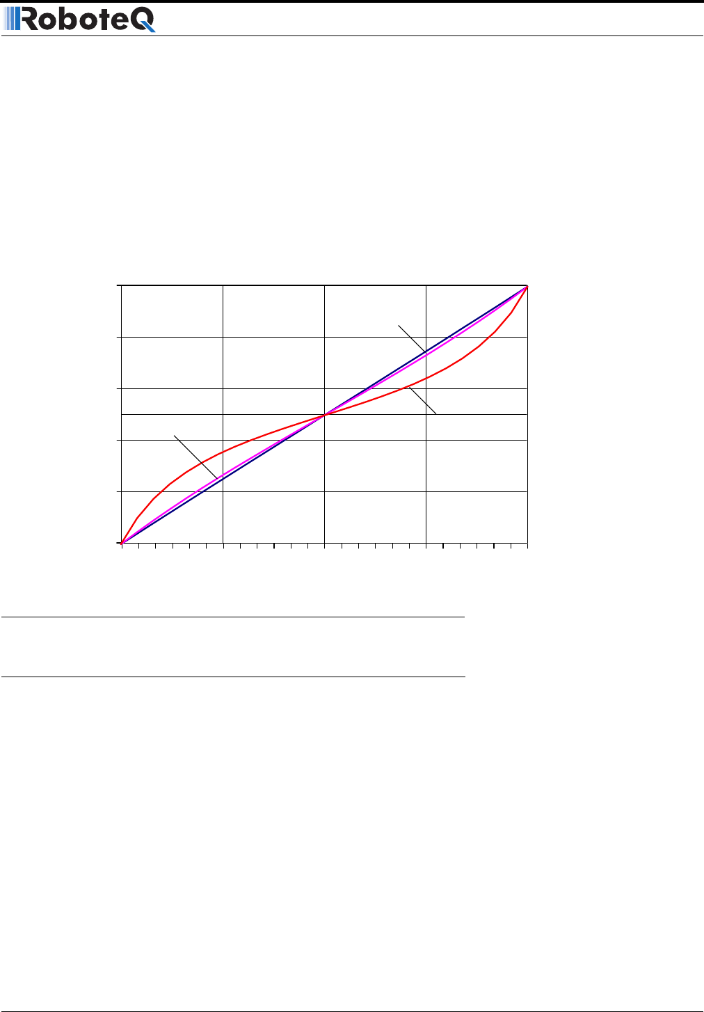
100K or higher potentiometer. Figure 86 shows how the output voltage varies at the vari-
ous potentiometer positions for three typical potentiometer values. Note that the effect is
an exponentiation that will cause the motors to start moving slowly and accelerate faster
as the potentiometer reaches either end.
This curve is actually preferable for most applications. It can be corrected or amplified by
changing the controller’s exponentiation parameters (see “Command Control Curves” on
page 48.
Analog Deadband Adjustment
The controller may be configured so that some amount of potentiometer or joystick travel
off its center position is required before the motors activate. The deadband parameter can
be one of 8 values, ranging from 0 to 7, which translate into a deadband of 0% to 16%.
Even though the deadband will cause some of the potentiometer movement around the
center position to be ignored, the controller will scale the remaining potentiometer move-
ment to command the motors from 0 to 100%.
Note that the scaling will also cause the motors to reach 100% at slightly less than 100%
of the potentiometer’s position. This is to ensure that 100% motor speed is achieved in all
circumstances. Table 22 below shows the effect of the different deadband parameter val-
ues. Changing the deadband parameter can be done using the controller’s switches (see
“Configuring the Controller using the Switches” on page 171) or the Roborun utility on a
PC (see “Loading, Changing Controller Parameters” on page 181).
0V
Min MaxCenter
100K Pot10K Pot
1K Pot
Potentiometer Position
Voltage at Input
1V
2V
3V
4V
5V
FIGURE 86. Effect of the controller’s internal resistors on various potentiometers