


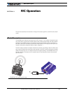
R/C Operation
110 AX2550 Motor Controller User’s Manual Version 1.9b. June 1, 2007
Selecting the R/C Input Mode
The R/C Input Mode is the factory default setting.
If the controller has been previously set to a different Input Mode, it will be necessary to
reset it to the R/C mode using one of the following methods:
• Restoring the factory defaults by pressing and holding the Program and Set but-
tons while powering on the controller until the LED display flashes
• Setting the “I” parameter to the value “0” using one of several methods described
in the chapters “Configuring the Controller using the Switches” on page 171,
“Using the Roborun Configuration Utility” on page 177, and “Accessing & Changing
Configuration Parameter in Flash” on page 143.
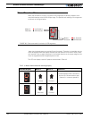
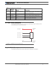
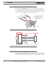
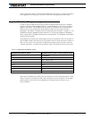
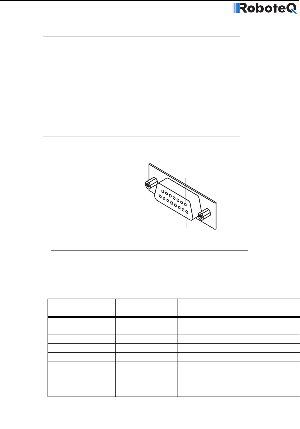
Connector I/O Pin Assignment (R/C Mode)
When used in R/C mode, the pins on the controller’s DB15 connector are mapped as
described in the table below.
TABLE 19. Connector pin-out in R/C mode
Pin
Number
Input or
Output Signal Description
1 and 9 Output Output C 2A Accessory Output C
2 Output RS232 data RS232 Data Logging Output
3 Input Ch 1 R/C radio Channel 1 pulses
4 Input Ch 2 R/C radio Channel 2 pulses
5 and 13 Power Out Ground Controller ground (-)
6 GND In Ground Optocoupler GND Input
Unused in RevB Hardware
7 +5V In +5V Optocoupler +5V Input
Unused in RevB Hardware
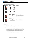
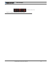
Pin1
8
15
9
FIGURE 69. Pin locations on the controller’s 15-pin connector