AX2550 Motor Controller User’s Manual 121
Data Logging in R/C Mode
Data Logging in R/C Mode
While in R/C Mode, the AX2550 will continuously send a string of characters on the RS232
output line. This string will contain 12 two-digit hexadecimal numbers representing the fol-
lowing operating parameters.
• Captured R/C Command 1 and 2
• Power Applied to Controller’s output stage
• Values applied to Analog inputs 1 and 2
• Amps on channel 1 and 2
• Internal Heat Sink temperatures 1 and 2
• Main Battery voltage
• Internal 12V voltage
• Encoder Speed or Position feedback, if encoder module is present.
The entire string is repeated every 200 milliseconds with the latest internal parameter val-
ues. This information can be logged using the Roborun Utility (see “Viewing and Logging
Data in Analog and R/C Modes” on page 192). It may also be stored in a PDA that can be
placed in the mobile robot.
The string and data format is described in “Analog and R/C Modes Data Logging String For-
mat” on page 166. The serial port’s output can be safely ignored if it is not required in the
application.
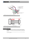
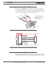
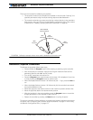
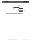
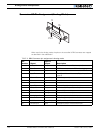
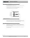
To read the output string while operating the controller with the R/C radio, you must mod-
ify the R/C cable to add an RS232 output wire and connector that will be connected to the
PC’s communication port. Figure 82 and below shows the wiring diagram of the modified
R/C cable for connection to a PC.
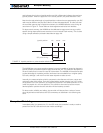
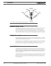
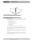
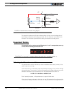
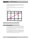
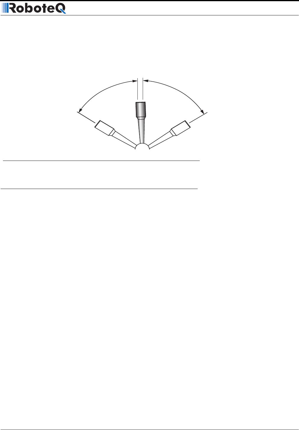
Output C
ON
Output C
OFF
Output C
OFF
FIGURE 81. Using Channel 3 to activate accessory outputs


