


General Operation
52 AX2550 Motor Controller User’s Manual Version 1.9b. June 1, 2007
The switch connection is described in “Connecting Switches or Devices to EStop/Invert
Input” on page 62. The switch must be such that it is in the open state in the normal situa-
tion and closed to signal an emergency stop command.
After and Emergency Stop condition, the controller must be reset or powered Off
and On to resume normal operation.
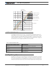
Inverted Operation
For robots that can run upside-down, the controller can be configured to reverse the motor
commands using a gravity activated switch when the robot is flipped. This feature is
enabled only in the mixed mode and when the switch is enabled with the proper configura-
tion of the “Input switch function” parameter. See “Programmable Parameters List” on
page 174.
The switch connection is described in “Connecting Switches or Devices to EStop/Invert
Input” on page 62. The switch must be such that it is in the open state when the robot is in
the normal position and closed when inverted. When the status of the switch has changed,
the controller will wait until the new status has remained stable for 0.5s before acknowl-
edging it and inverting the commands. This delay is to prevent switch activation triggered
by hits and bounces which may cause the controller to erroneously invert the commands.
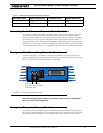
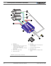
Special Use of Accessory Digital Inputs
The AX2550 includes two general purpose digital inputs identified as Input E and Input F.
When an Encoder Module is installed, input E is disabled. The location of these inputs on
the DB15 connector can be found in the section “I/O List and Pin Assignment” on
page 58, while the electrical signal needed to activate them is shown on “Connecting
Switches or Devices to Input F” on page 61.
By default, these inputs are ignored by the controller. However, the AX2550 may be config-
ured to cause either of the following actions:
• Activate the buffered Output C
• Turn Off/On the power MOSFET transistors
These alternate modes can only be selected using the Roborun Utility (see “Control Set-
tings” on page 181. Each of these modes is detailed below.
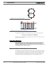
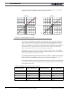
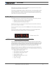
Using the Inputs to Activate the Buffered Output
When this setting is selected, the buffered Output C will be On when the Input line is
pulled to Ground (0V). The Output will be Off when the Input is pulled high.
This function makes it possible to drive solenoids or other accessories up to 2A at 24V
using a very low current switch, for example.
Using the Inputs to turn Off/On the Power MOSFET transistors
When this setting is selected, the controller’s Power MOSFET transistors will be active,
and the controller will be operating normally, only when the input is pulled to ground.