


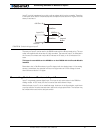

Connecting Sensors and Actuators to Input/Outputs
60 AX2550 Motor Controller User’s Manual Version 1.9b. June 1, 2007
This output can be turned On and Off using the Channel 3 Joystick when in the R/C mode.
See “Activating the Accessory Outputs” on page 120 for more information.
When the controller is used in RS232 mode, this output can be turned On and Off using
the !C (On) and !c (Off) command strings. See “Controller Commands and Queries” on
page 138 for more information.
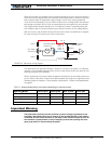
Important warning:
Overvoltage spikes induced by switching inductive loads, such as solenoids or
relays, will destroy the transistor unless a protection diode is used.
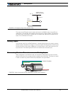
Connecting Switches or Devices to Input E
Input E is a general purpose, digital input. This input is only available if no encoder module
is present and is active when in the RS232 and Analog modes. In R/C mode, this line is
used as the radio channel 3 input.
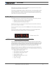
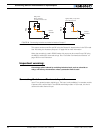
5 to
24V
DC
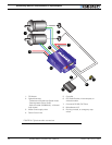
Output C 1,9
Internal
Transistor
Relay, Valve
Motor, Solenoid
or other Inductive Load
Ground 5
+
-
5 to
24V
DC
Output C 1,9
Internal
Transistor
Lights, LEDs, or any other
non-inductive load
Ground 5
+
-
FIGURE 28. Connecting inductive and resistive loads to Output C