


R/C Operation
118 AX2550 Motor Controller User’s Manual Version 1.9b. June 1, 2007
Command Control Curves
The AX2550 can also be set to translate the joystick motor commands so that the motors
respond differently depending on whether the joystick is near the center or near the
extremes. Five different exponential or logarithmic translation curves may be applied.
Since this feature applies to the R/C, Analog and RS232 modes, it is described in detail in
“Command Control Curves” on page 48, in the General Operation section of this manual.
Left/Right Tuning Adjustment
When operating in mixed mode with one motor on each side of the robot, it may happen
that one motor is spinning faster than the other one at identically applied power, causing
the vehicle to pull to the left or to the right.
To compensate for this, the AX2550 can be made to give one side up to 10% more power
than the other at the same settings. This capability is described in detail in “Left / Right
Tuning Adjustment” on page 49, in the General Operation section of this manual.
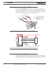
Joystick Calibration
This feature allows you to program the precise minimum, maximum and center joystick
positions of your R/C transmitter into the controller’s memory. This feature will allow you to
use the full travel of your joystick (i.e. minimum = 100% reverse, maximum = 100% for-
ward). It also ensures that the joystick’s center position does indeed correspond to a “0”
motor command value.
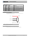
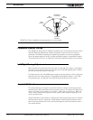
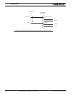
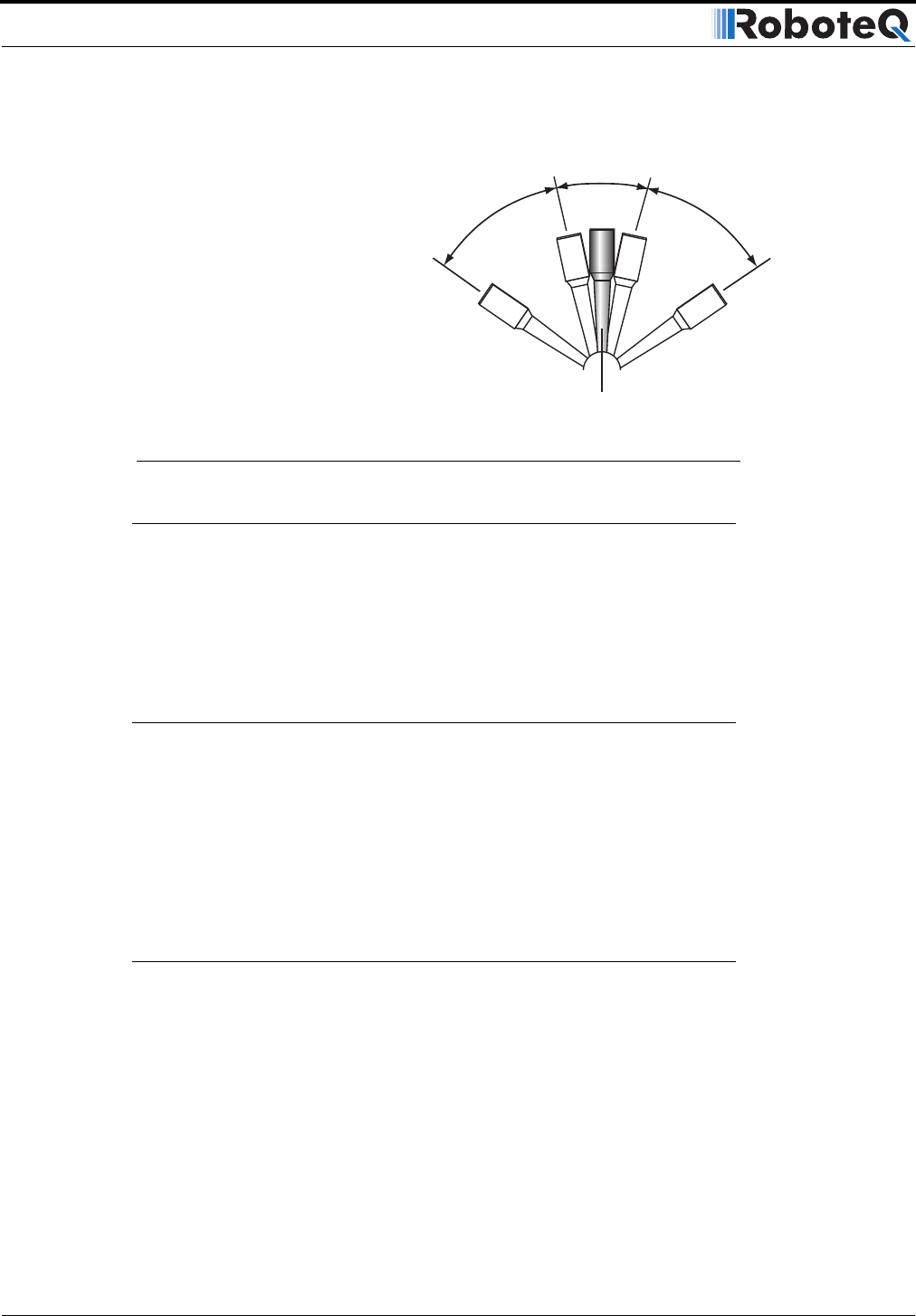
Joystick calibration is also useful for modifying the active joystick travel area. For example,
the figure below shows a transmitter whose joystick’s center position has been moved
back so that the operator has a finer control of the speed in the forward direction than in
the reverse position.
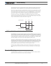
Centered
Position
Deadband
(no action)
Min
Forward
Min
Reverse
Max
Forward
Max
Reverse
FIGURE 79. Effect of deadband on joystick position vs. motor speed