


AX2550 Motor Controller Overview
26 AX2550 Motor Controller User’s Manual Version 1.9b. June 1, 2007
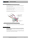
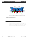
The motors are driven using high-efficiency Power MOSFET transistors controlled using
Pulse Width Modulation (PWM) at 16kHz. The AX2550 power stages can operate from 12
to 40VDC and can sustain up to 120A of controlled current, delivering up to 4,800W
(approximately 6 HP) of useful power to each motor.
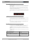
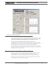
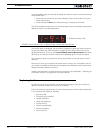
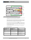
The many programmable options of the AX2550 are easily configured using the supplied
PC utility or one-touch Program and Set buttons and a 7-segment LED display. Once pro-
grammed, the configuration data are stored in the controller's non-volatile memory, elimi-
nating the need for cumbersome and unreliable jumpers.
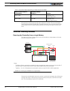
The AX2850 is the AX2550 controller fitted with a dual channel optical encoder input mod-
ule. Optical Encoders allow precise motor speed and position measurement and enable
advance robotic applications.
Technical features
Fully Digital, Microcontroller-based Design
• Multiple operating modes
• Fully programmable using either built-in switches and 7 segment display or through
connection to a PC
• Non-volatile storage of user configurable settings
• Simple operation
• Software upgradable with new features
Multiple Command Modes
• Radio-Control Pulse-Width input
• Serial port (RS-232) input
• 0-5V Analog Command input
Multiple Advanced Motor Control Modes
• Independent operation on each channel
• Mixed control (sum and difference) for tank-like steering
• Open Loop or Closed Loop Speed mode
• Position control mode for building high power position servos
• Modes selectable independently for each channel
Automatic Joystick Command Corrections
• Joystick min, max and center calibration
• Selectable deadband width
• Selectable exponentiation factors for each joystick
• 3rd R/C channel input for accessory output activation (disabled when encoder mod-
ule present)
Special Function Inputs/Outputs
• 2 Analog inputs. Used as: