


Two Port 10/100 Managed Ethernet Switch with 16-Bit Non-PCI CPU Interface
Datasheet
SMSC LAN9311/LAN9311i 115 Revision 1.4 (08-19-08)
DATASHEET
should be unique. If both are set to the same value, VLAN1 is given higher precedence and the
maximum legal frame length is set to 1522.
9.4 Address Filtering
The Ethernet address fields of an Ethernet packet consist of two 6-byte fields: one for the destination
address and one for the source address. The first bit of the destination address signifies whether it is
a physical address or a multicast address.
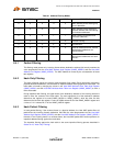
The Host MAC address check logic filters the frame based on the Ethernet receive filter mode that has
been enabled. The various filter modes of the Host MAC are specified based on the state of the control
bits in the Host MAC Control Register (HMAC_CR), as shown in Table 9.1. Please refer to the Section
14.3.1, "Host MAC Control Register (HMAC_CR)," on page 272 for more information on this register.
If the frame fails the filter, the Host MAC does not receive the packet. The host has the option of
accepting or ignoring the packet.
Note: This filtering function is performed after any switch fabric filtering functions. The user must
ensure the switch filtering is setup properly to allow packets to be passed to the Host MAC for
further filtering.
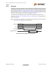
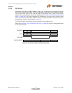
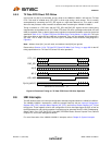
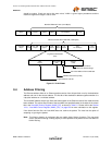
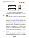
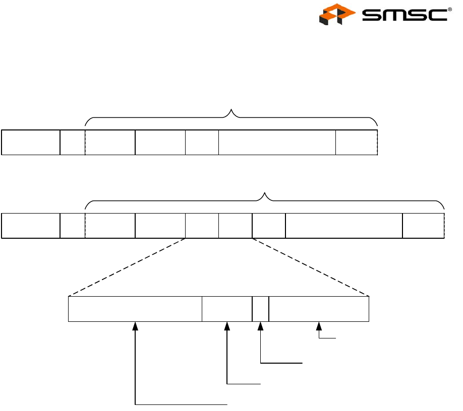
Figure 9.1 VLAN Frame
Preamble
7 Bytes
SOF
1 Byte
Dest. Addr.
6 Bytes
Source Addr.
6 Bytes
Type
2 Bytes
Data
46-1500 Bytes
FCS
4 Bytes
Standard Ethernet Frame (1518 Bytes)
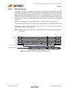
Preamble
7 Bytes
SOF
1 Byte
Dest. Addr.
6 Bytes
Source Addr.
6 Bytes
Type
2 Bytes
Data
46-1500 Bytes
FCS
4 Bytes
Ethernet Frame with VLAN TAG (1522 Bytes)
TPID
2 Bytes
Type
2 Bytes
TPID
2 Bytes
VLAN ID
12 Bits
User Priority
3 Bits
CFI
1 Bit
Tag Control Information
(TCI)
Defines the VLAN to
which the frame belongs
Canonical Address Format Indicator
Indicates the frame’s priority
Tag Protocol ID: \x81-00