


Two Port 10/100 Managed Ethernet Switch with 16-Bit Non-PCI CPU Interface
Datasheet
Revision 1.4 (08-19-08) 32 SMSC LAN9311/LAN9311i
DATASHEET
Note 3.3 The IS buffer type is valid only during the time specified in Section 15.5.2, "Reset and
Configuration Strap Timing," on page 446.
Note 3.4 Configuration strap values are latched on power-on reset or nRST de-assertion.
Configuration strap pins are identified by an underlined symbol name. Refer to Section
4.2.4, "Configuration Straps," on page 40 for more information.
Note 3.5 The IS buffer type is valid only during the time specified in Section 15.5.2, "Reset and
Configuration Strap Timing," on page 446 and when in I
2
C mode.
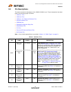
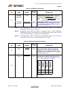
101
EEPROM
Microwire
Chip Select
EECS O8 EEPROM Microwire Chip Select: In Microwire
EEPROM mode (EEPROM_TYPE
= 0), this pin is
the Microwire EEPROM chip select output.
Note: In I
2
C mode (EEPROM_TYPE=1), this pin
is not used and is driven low.
EEPROM
Size Strap 0
EEPROM_SIZE_0
IS
Note 3.3
EEPROM Size Strap 0: Configures the low bit of
the EEPROM size range as specified in Section
10.2, "I2C/Microwire Master EEPROM Controller,"
on page 138. See Note 3.4.
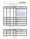
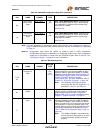
Table 3.6 Dedicated Configuration Strap Pins
PIN NAME SYMBOL
BUFFER
TYPE DESCRIPTION
67
LED Enable
Strap
LED_EN
IS
(PU)
LED Enable Strap: Configures the default value
for the LED_EN bits in the LED Configuration
Register (LED_CFG). When latched low, all 8
LED/GPIO pins are configured as GPIOs. When
latched high, all 8 LED/GPIO pins are configured
as LEDs. See Note 3.6.
68
PHY Address
Strap
PHY_ADDR_SEL
IS
(PU)
PHY Address Select Strap: Configures the default
MII management address values for the PHYs
(Virtual, Port 1, and Port 2) as detailed in Section
7.1.1, "PHY Addressing," on page 82.
See Note 3.6.
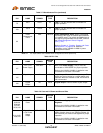
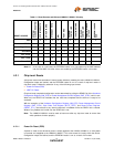
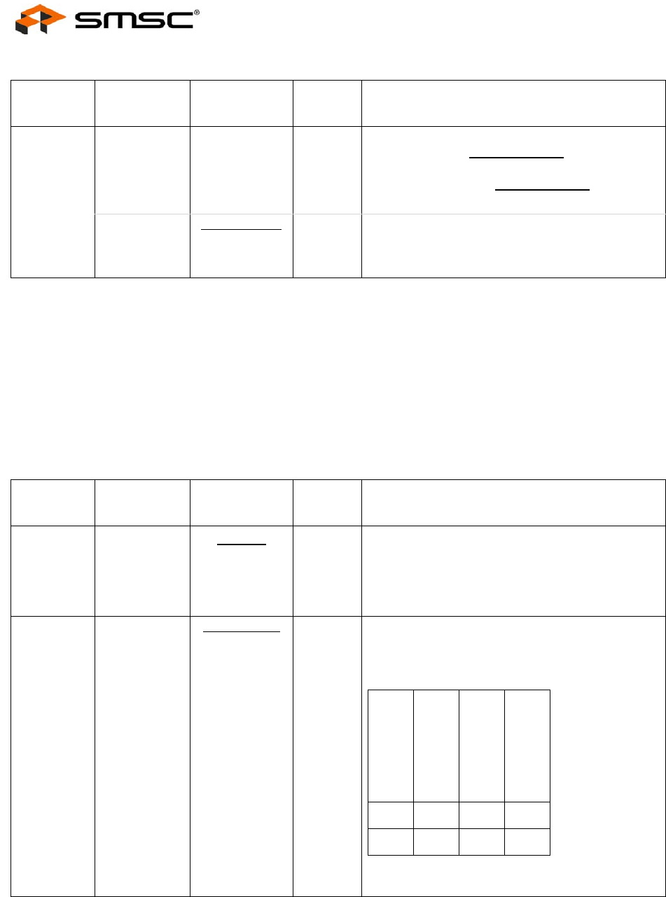
Table 3.5 EEPROM Pins (continued)
PIN NAME SYMBOL
BUFFER
TYPE DESCRIPTION
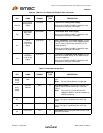
PHY_ADDR_SEL
VALUE
VIRTUAL PHY
ADDRESS
PORT 1 PHY
ADDRESS
PORT 2 PHY
ADDRESS
0 012
1 123