


Two Port 10/100 Managed Ethernet Switch with 16-Bit Non-PCI CPU Interface
Datasheet
SMSC LAN9311/LAN9311i 63 Revision 1.4 (08-19-08)
DATASHEET
Total multicast packets (Section 14.5.2.37, on page 360)
Total packets with a late collision (Section 14.5.2.38, on page 361)
Total packets with excessive collisions (Section 14.5.2.39, on page 362)
Total packets with a single collision (Section 14.5.2.40, on page 363)
Total packets with multiple collisions (Section 14.5.2.41, on page 364)
Total collision count (Section 14.5.2.42, on page 365)
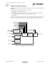
6.4 Switch Engine (SWE)
The switch engine (SWE) is a VLAN layer 2 (link layer) switching engine supporting 3 ports. The SWE
supports the following types of frame formats: untagged frames, VLAN tagged frames, and priority
tagged frames. The SWE supports both the 802.3 and Ethernet II frame formats.
The SWE provides the control for all forwarding/filtering rules. It handles the address learning and
aging, and the destination port resolution based upon the MAC address and VLAN of the packet. The
SWE implements the standard bridge port states for spanning tree and provides packet metering for
input rate control. It also implements port mirroring, broadcast throttling, and multicast pruning and
filtering. Packet priorities are supported based on the IPv4 TOS bits and IPv6 Traffic Class bits using
a DIFFSERV Table mapping, the non-DIFFSERV mapped IPv4 precedence bits, VLAN priority using
a per port Priority Regeneration Table, DA based static priority, and Traffic Class mapping to one of 4
QoS transmit priority queues.
The following sections detail the various features of the switch engine.
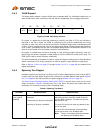
6.4.1 MAC Address Lookup Table
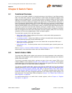
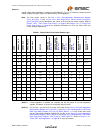
The Address Logic Resolution (ALR) maintains a 1024 entry MAC Address Table. The ALR searches
the table for the destination MAC address. If the search finds a match, the associated data is returned
indicating the destination port or ports, whether to filter the packet, the packets priority (used if
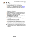
enabled), and whether to override the ingress and egress spanning tree port state. Figure 6.3 displays
the ALR table entry structure. Refer to the Switch Engine ALR Write Data 0 Register
(SWE_ALR_WR_DAT_0) and Switch Engine ALR Write Data 1 Register (SWE_ALR_WR_DAT_1) for
detailed descriptions of these bits.
Figure 6.3 ALR Table Entry Structure
55
Age /
Override
Valid
56
Static
54
Filter
53
Priority
52 51
Port
50 49 48
MAC Address
47 0
...
Bit