


Two Port 10/100 Managed Ethernet Switch with 16-Bit Non-PCI CPU Interface
Datasheet
SMSC LAN9311/LAN9311i 197 Revision 1.4 (08-19-08)
DATASHEET
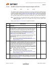
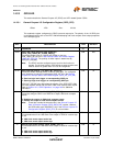
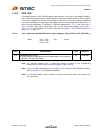
14.2.3.4 LED Configuration Register (LED_CFG)
This read/write register configures the GPIO[7:0] pins as LED[7:0] pins and sets their functionality.
Note 14.2 The default value of this field is determined by the configuration strap LED_fun_strap[1:0].
Configuration strap values are latched on power-on reset or nRST de-assertion. Some
configuration straps can be overridden by values from the EEPROM Loader. Refer to
Section 4.2.4, "Configuration Straps," on page 40 for more information.
Note 14.3 The default value of this field is determined by the configuration strap LED_en_strap[7:0].
Configuration strap values are latched on power-on reset or nRST de-assertion. Some
configuration straps can be overridden by values from the EEPROM Loader. Refer to
Section 4.2.4, "Configuration Straps," on page 40 for more information.
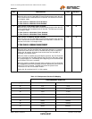
Offset: 1BCh Size: 32 bits
BITS DESCRIPTION TYPE DEFAULT
31:10 RESERVED RO -
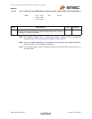
9:8
LED Function 1-0 (LED_FUN[1:0])
These bits control the function associated with each LED pin as shown in
Table 13.1 of Section 13.3, "LED Operation," on page 165.
Note: In order for these assignments to be valid, the particular pin must
be enabled as an LED output pin via the LED_EN[7:0] bits of this
register.
R/W Note 14.2
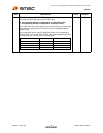
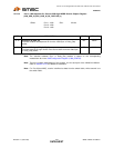
7:0
LED Enable 7-0 (LED_EN[7:0])
This field toggles the functionality of the GPIO[7:0] pins between GPIO and
LED.
0: Enables the associated pin as a GPIO signal
1: Enables the associated pin as a LED output
R/W Note 14.3