


Two Port 10/100 Managed Ethernet Switch with 16-Bit Non-PCI CPU Interface
Datasheet
SMSC LAN9311/LAN9311i 167 Revision 1.4 (08-19-08)
DATASHEET
Chapter 14 Register Descriptions
This section describes the various LAN9311/LAN9311i control and status registers (CSR’s). These
registers are broken into 5 categories. The following sections detail the functionality and accessibility
of all the LAN9311/LAN9311i registers within each category:
Section 14.1, "TX/RX FIFO Ports," on page 168
Section 14.2, "System Control and Status Registers," on page 169
Section 14.3, "Host MAC Control and Status Registers," on page 271
Section 14.4, "Ethernet PHY Control and Status Registers," on page 287
Section 14.5, "Switch Fabric Control and Status Registers," on page 309
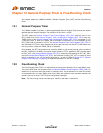
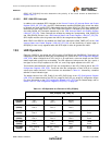
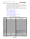
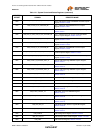
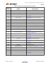
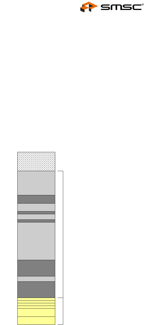
Figure 14.1 contains an overall base register memory map of the LAN9311/LAN9311i. This memory
map is not drawn to scale, and should be used for general reference only.
Note: Register bit type definitions are provided in Section 1.3, "Register Nomenclature," on page 19.
Note: Not all LAN9311/LAN9311i registers are memory mapped or directly addressable. For details
on the accessibility of the various LAN9311/LAN9311i registers, refer the register sub-sections
listed above.
Figure 14.1 LAN9311/LAN9311i Base Register Memory Map
RX Data FIFO Port
& Alias Ports
TX Data FIFO Port
& Alias Ports
RX Status FIFO Port
RX Status FIFO PEEK
TX Status FIFO Port
TX Status FIFO PEEK
Base + 000h
020h
040h
044h
048h
04Ch
100h
TX/RX FIFOs
RESERVED
2E0h
...
2DCh
3FFh
Switch CSR Direct Data
Registers
200h
...
System CSRs
03Ch
01Ch
050h
1588 Registers
Virtual PHY Registers
1C0h
1DCh
19Ch
Switch Interface Registers
1ACh
1B0h
Host MAC Interface Registers
0A4h
0A8h