Two Port 10/100 Managed Ethernet Switch with 16-Bit Non-PCI CPU Interface
Datasheet
Revision 1.4 (08-19-08) 254 SMSC LAN9311/LAN9311i
DATASHEET
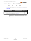
Note 14.27 The reserved bits 31-16 are used to pad the register to 32-bits so that each register is on
a DWORD boundary. When accessed serially (through the MII management protocol), the
register is 16-bits wide.
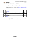
Note 14.28 The Virtual PHY does not support next page capability. This bit value will always be 0.
Note 14.29 The Remote Fault bit is not useful since there is no actual link partner to send a fault to.
Note 14.30 The Pause bit defaults to 1 if the manual_FC_strap_mii strap is low, and 0 if the
manual_FC_strap_mii strap is high. Configuration strap values are latched upon the de-
assertion of a chip-level reset as described in Section 4.2.4, "Configuration Straps," on
page 40.
Note 14.31 Virtual 100BASE-T4 is not supported.
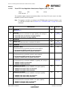
Note 14.32 The Virtual PHY supports only IEEE 802.3. Only a value of 00001b should be used in this
field.
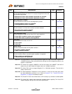
5
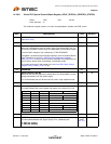
10BASE-T Half Duplex
This bit determines the advertised 10BASE-T half duplex capability.
0: 10BASE-T half duplex ability not advertised
1: 10BASE-T half duplex ability advertised
R/W 1b
4:0
Selector Field
This field identifies the type of message being sent by Auto-Negotiation.
00001: IEEE 802.3
R/W 00001b
Note 14.32
BITS DESCRIPTION TYPE DEFAULT


