


Two Port 10/100 Managed Ethernet Switch with 16-Bit Non-PCI CPU Interface
Datasheet
Revision 1.4 (08-19-08) 198 SMSC LAN9311/LAN9311i
DATASHEET
14.2.4 EEPROM
This section details the EEPROM related System CSR’s. These registers should only be used if an
EEPROM has been connected to the LAN9311/LAN9311i. Refer to chapter Section 10.2,
"I2C/Microwire Master EEPROM Controller," on page 138 for additional information on the various
modes (I
2
C and Microwire) of the EEPROM Controller (EPC).
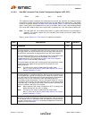
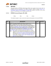
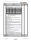
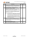
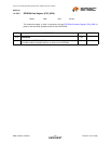
14.2.4.1 EEPROM Command Register (E2P_CMD)
This read/write register is used to control the read and write operations of the serial EEPROM.
Offset: 1B4h Size: 32 bits
BITS DESCRIPTION TYPE DEFAULT
31 EEPROM Controller Busy (EPC_BUSY)
When a 1 is written into this bit, the operation specified in the
EPC_COMMAND field of this register is performed at the specified
EEPROM address. This bit will remain set until the selected operation is
complete. In the case of a read, this indicates that the Host can read valid
data from the EEPROM Data Register (E2P_DATA). The E2P_CMD and
E2P_DATA registers should not be modified until this bit is cleared. In the
case where a write is attempted and an EEPROM is not present, the
EPC_BUSY bit remains set until the EEPROM Controller Timeout
(EPC_TIMEOUT) bit is set. At this time the EPC_BUSY bit is cleared.
Note: EPC_BUSY is set immediately following power-up, or pin reset, or
DIGITAL_RST reset. This bit is also set following the settings of the
SRST bit in the Hardware Configuration Register (HW_CFG). After
the EEPROM Loader has finished loading, the EPC_BUSY bit is
cleared. Refer to chapter Section 10.2.4, "EEPROM Loader," on
page 150 for more information.
R/W
SC
0b