


Two Port 10/100 Managed Ethernet Switch with 16-Bit Non-PCI CPU Interface
Datasheet
Revision 1.4 (08-19-08) 78 SMSC LAN9311/LAN9311i
DATASHEET
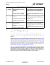
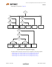
6.5.4 Transmit Priority Queue Servicing
When a transmit queue is non-empty, it is serviced and the packet is read from the buffer RAM and
sent to the transmit MAC. If there are multiple queues that require servicing, one of two methods may
be used: fixed priority ordering, or weighted round-robin ordering. If the Fixed Priority Queue Servicing
bit in the Buffer Manager Configuration Register (BM_CFG) is set, a strict order, fixed priority is
selected. Transmit queue 3 has the highest priority, followed by 2, 1, and 0. If the Fixed Priority Queue
Servicing bit in the Buffer Manager Configuration Register (BM_CFG) is cleared, a weighted round-
robin order is followed. Assuming all four queues are non-empty, the service is weighted with a 9:4:2:1
ratio (queue 3,2,1,0). The servicing is blended to avoid burstiness (e.g. queue 3, then queue 2, then
queue 3, etc.).
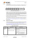
6.5.5 Egress Rate Limiting (Leaky Bucket)
For egress rate limiting, the leaky bucket algorithm is used on each output priority queue. For each
output port, the bandwidth that is used by each priority queue can be limited. If any egress queue
receives packets faster than the specified egress rate, packets will be accumulated in the packet
memory. After the memory is used, packet dropping or flow control will be triggered.
Note: Egress rate limiting occurs before the Transmit Priority Queue Servicing, such that a lower
priority queue will be serviced if a higher priority queue is being rate limited.
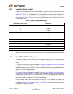
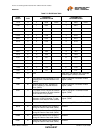
The egress limiting is enabled per priority queue. After a packet is selected to be sent, its length is
recorded. The switch then waits a programmable amount of time, scaled by the packet length, before
servicing that queue once again. The amount of time per byte is programmed into the Buffer Manager
Egress Rate registers (refer to Section 14.5.4.14 through Section 14.5.4.19 for detailed register
definitions). The value programmed is in approximately 20 nS per byte increments. Typical values are
listed in Table 6.5. When a port is transmitting at 10 Mbps, any setting above 39 has the effect of not
limiting the rate.
Note 6.3 These are the unlimited max bandwidths when IFG and preamble are taken into account.
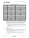
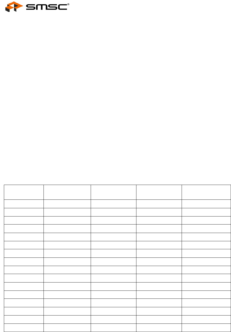
Table 6.5 Typical Egress Rate Settings
EGRESS RATE
SETTING TIME PER BYTE
BANDWIDTH @
64 BYTE PACKET
BANDWIDTH @
512 BYTE PACKET
BANDWIDTH @
1518 BYTE PACKET
0-3 80 nS 76 Mbps (Note 6.3) 96 Mbps (Note 6.3)99 Mbps (Note 6.3)
4 100 nS 66 Mbps 78 Mbps 80 Mbps
5 120 nS 55 Mbps 65 Mbps 67 Mbps
6 140 nS 48 Mbps 56 Mbps 57 Mbps
7 160 nS 42 Mbps 49 Mbps 50 Mbps
9 200 nS 34 Mbps 39 Mbps 40 Mbps
12 260 nS 26 Mbps 30 Mbps 31 Mbps
19 400 nS 17 Mbps 20 Mbps 20 Mbps
39 800 nS 8.6 Mbps 10 Mbps 10 Mbps
78 1580 nS 4.4 Mbps 5 Mbps 5 Mbps
158 3180 nS 2.2 Mbps 2.5 Mbps 2.5 Mbps
396 7940 nS 870 Kbps 990 Kbps 1 Mbps
794 15900 nS 440 Kbps 490 Kbps 500 Kbps
1589 31800 nS 220 Kbps 250 Kbps 250 Kbps
3973 79480 nS 87 Kbps 98 Kbps 100 Kbps
7947 158960 nS 44 Kbps 49 Kbps 50 Kbps