


AP-5131 Access Point Product Reference Guide
2-4
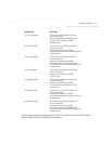
The Symbol power injector (Part No. AP-PSBIAS-1P2-AFR) is included in certain orderable
configurations, but can be added to any configuration. For more information on the Symbol power
injector, see Symbol Power Injector System on page 2-8.
For an overview on the optional antennae available for the AP-5131, see Antenna Options on page 2-
5. For detailed specifications on the 2.4 GHz and 5.2 GHz antenna suite, see 2.4 GHz Antenna Matrix
on page A-4 and 5.2 GHz Antenna Matrix on page A-4.
2.3 Requirements
The minimum installation requirements for a single-cell, peer-to-peer network:
• AP-5131 (either the dual or single radio model)
• AP-5131 48 Volt Power Supply (Part No. 50-24000-050) or Symbol power injector
(Part No. AP-PSBIAS-1P2-AFR)
• a power outlet
• Dual-Band Antennae (Part No. ML-2452-APA2-01)
.
2.4 Placement of the AP-5131
For optimal performance, install the AP-5131 away from transformers, heavy-duty motors, fluorescent
lights, microwave ovens, refrigerators and other industrial equipment. Signal loss can occur when
NOTE A standard Symbol 48 Volt Power Adapter (Part No. 50-24000-050) is
recommended with AP-5131 product SKUs that do not include the Symbol
power injector.
CAUTION Using an antenna other than the Dual-Band Antenna (Part No.
ML-2452-APA2-01) could render the AP-5131’s Rogue AP Detector
Mode feature inoperable. Contact your Symbol sales associate for
specific information.
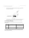
NOTE The AP-5131 optimally uses 2 antennae for the single-radio model and 4
antennae for the dual-radio model.
!