AP-5131 Access Point Product Reference Guide
2-6
suite supporting the 2.4 GHz band and another antenna suite supporting the 5.2 GHz band. Select an
antenna model best suited to the intended operational environment of your AP-5131.
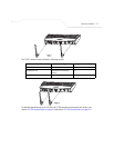
Antenna connectors for Radio 1 are located in a different location from the Radio 2 antenna
connectors. On single radio versions, the R-SMA connectors can support both bands and should be
connected to a R-SMA dual-band antenna or an appropriate single band antenna. If necessary a R-
SMA to R-BNC adapter (Part No. 25-72178-01) can be purchased separately from Symbol.
The 2.4 GHz antenna suite includes the following models:
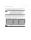
NOTE On a single-radio AP-5131, Radio 1 can be configured to be either a 2.4
GHz or 5.2 GHz radio. On a dual-radio model, Radio 1 refers to the AP-
5131’s 2.4 GHz radio and Radio 2 refers to the AP-5131 5.2 GHz radio.
However, there could be some cases where a dual-radio AP-5131 is
performing a Rogue AP detector function. In this scenario, the AP-5131 is
receiving in either 2.4 GHz or 5.2 GHz over the Radio 1 or Radio 2
antennae depending on which radio is selected for the scan.
Symbol Part Number Antenna Type Nominal Net Gain (dBi)
ML-2499-11PNA2-01R Wide Angle Directional 8.5
ML-2499-HPA3-01R Omni-Directional Antenna 3.3
ML-2499-BYGA2-01R Yagi Antenna 13.9
ML-2452-APA2-01 Dual-Band 3.0
NOTE An additional adapter is required to use ML-2499-11PNA2-01 and
ML-2499-BYGA2-01 model antennae. Please contact Symbol for more
information.


