


AP-5131 Access Point Product Reference Guide
2-14
8. Cable the AP-5131 using either the Symbol power injector solution or an approved line cord
and power supply.
For Symbol power injector installations:
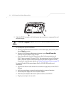
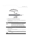
a. Connect a RJ-45 Ethernet cable between the network data supply (host) and the Power
Injector Data In connector.
b. Connect a RJ-45 Ethernet cable between the power injector Data & Power Out
connector and the AP-5131 LAN port.
c. Ensure the cable length from the Ethernet source (host) to the power injector and
AP-5131 does not exceed 100 meters (333 ft). The power injector has no On/Off power
switch. The power injector receives power as soon as AC power is applied. For more
information on using the power injector, see Symbol Power Injector System on page 2-8.
For standard Symbol 48-Volt Power Adapter (Part No. 50-24000-050) and line cord
installations:
a. Connect RJ-45 Ethernet cable between the network data supply (host) and the AP-5131
LAN port.
b. Verify the power adapter is correctly rated according the country of operation.
c. Connect the power supply line cord to the power adapter.
d. Attach the power adapter cable into the power connector on the AP-5131.
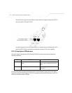
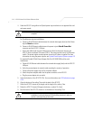
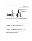
CAUTION Both the Dual and Single Radio model AP-5131s use RSMA type
antenna connectors. On the Dual Radio AP-5131, a single dot on the
antenna connector indicates the primary antenna for both Radio 1 (2.4
GHz) and Radio 2 (5.2 GHz). Two dots designate the secondary
antenna for both Radio 1 and Radio 2. On Single Radio models, a
single dot on the antenna connector indicates the primary antenna for
Radio 1, and two dots designate the secondary antenna for Radio 1.
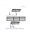
NOTE The AP-5131 must be mounted with the RJ45 cable connector oriented
upwards to ensure proper operation.
CAUTION Do not supply power to the AP-5131 until the cabling of the unit is
complete.
!
!