


4 Replacement Procedures 4.8 Display assembly
Installing the display assembly
The following describes the procedure for installing the display assembly (See Figure 4-14 to
4-18).
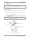
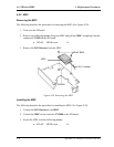
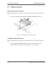
1. Connect the wireless LAN antenna cables (Main (white cable) and Aux (black
cable)) to the connectors on the wireless LAN board.
2. Install the wireless LAN cover and fix it with the following screw. Pass the wireless
LAN cables inside the guide of the wireless LAN cover.
• M2×4Z BIND screw x1
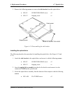
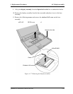
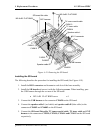
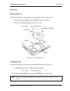
3. Install the display assembly on the base assembly.
NOTE: Make sure there is no cable caught between the display assembly and base
assembly.
4. Secure the display assembly with the following screws.
• M2.5×6B FLAT BIND screw x2
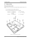
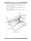
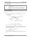
5. Pass the wireless LAN antenna cables through the guide on the middle frame from the
wireless LAN board side and fix them with the insulators. The excess part of the
cables should be kept under the frame of upper side of the slot.
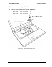
6. Connect the SJ board flat cable to the connector CN9550 on the sound board.
7. Connect the LCD harness to the connector PJ5600 on the system board.
8. Connect the touch pad cable to the CN3201 on the system board.
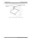
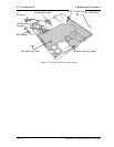
9. Install the harness cover from the display side and secure it with the following screw.
• M2.5×10B FLAT BIND screw x1
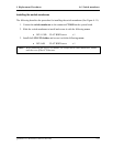
10. Secure the base assembly with the following screws.
NOTE: Be sure to apply the locktight to the screws with mark “+L” in the figure.
• M2.5×10B FLAT BIND screw x12 (“10” in the figure)
• M2.5×10B FLAT BIND screw x2 (“10+L” in the figure)
(Locktight)
• M2.5×4B FLAT BIND screw x1 (“4” in the figure)
QOSMIO F10 Maintenance Manual (960-498) 4-31