


ADCP-50-304 • Issue 19 • June 1999 • Section 1: Introduction
Page 1-1
© 1999, ADC Telecommunications, Inc.
SECTION 1: INTRODUCTION
1 GENERAL. . . . . . . . . . . . . . . . . . . . . . . . . . . . . . . . . . . . . . . . . . . . . . . . . . . . . . . . . . . . . . . . . . . . . . . . . . . .1-1
2 PURPOSE AND SCOPE . . . . . . . . . . . . . . . . . . . . . . . . . . . . . . . . . . . . . . . . . . . . . . . . . . . . . . . . . . . . . . . . . . .1-2
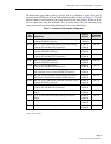
2.1 PatchSwitch Assembly Configurations . . . . . . . . . . . . . . . . . . . . . . . . . . . . . . . . . . . . . . . . . . . . . . . . . .1-2
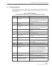
2.2 PatchSwitch Equipment . . . . . . . . . . . . . . . . . . . . . . . . . . . . . . . . . . . . . . . . . . . . . . . . . . . . . . . . . . . .1-5
3 SPECIFICATIONS. . . . . . . . . . . . . . . . . . . . . . . . . . . . . . . . . . . . . . . . . . . . . . . . . . . . . . . . . . . . . . . . . . . . . . .1-9
3.1 DMPS-10 AC Power Supply. . . . . . . . . . . . . . . . . . . . . . . . . . . . . . . . . . . . . . . . . . . . . . . . . . . . . . . . . .1-9
_________________________________________________________________________________________________________
1 GENERAL
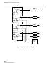
ADC PatchSwitch Digital Patching with RS-232/V.24, X.21, and V.35 Switching equipment,
hereinafter referred to as PatchSwitch or PS, provides convenient access to RS-232 (ANSI/EIA-
232) or CCITT V.24, X.21, or V.35 circuits for patching or switching to allow monitoring,
testing, and reconfiguring of a communications network. The V.35 description is located in
Section 3. The X.21 description is located in Section 4.
The PatchSwitch product line is a flexible, modular system providing the following features:
1. Monitoring of digital communications leads without circuit interruption;
2. Line access and switching on data communications circuit directed toward two (A/B)
equipments at the DTE end and as directed toward the modem at the DCE end;
3. Loss of monitored signal alarming circuits which identify the down circuit with either or
both visual and audible indications;
4. Optional signal monitoring and alarming of eight different RS-232 signal lines;
5. Optional interlocking in groups of two to 16 modules with A/B switching;
6. Optional interlocking in groups of two to 16 chassis with A/B switching;
7. Optional test module with three (3) RS-232 female ports for convenient interface with
compatible test equipment, with or without lead status monitoring LEDs (8-leads
monitored);
8. Flexibility of the modular system approach allows the addition of chassis and modules and
the interchange of modules on a single line basis;
9. Module replacement or removal with no need for rear cable disconnection;
10. All female DTE and DCE connectors or female DTE and male DCE connectors;
11. High density chassis occupies 7 inches (17.78 cm) in height within a standard 19-inch
(48.26 cm) wide rack;
Content Page
Note:
The PatchSwitch equipment described in this manual conforms to EIA/CCITT (RS-
232/Recommendation V.24), interface between Data Terminal Equipment (DTE) and Data
Communication Equipment (DCE) known as the Serial Binary Data Interchange or SBDI.