


ADCP-50-304 • Issue 19 • June 1999 • Section 3: PatchSwitch V.35
Page 3-8
© 1999, ADC Telecommunications, Inc.
5 HARDWARE INSTALLATION
Remove power to the shelf by turning off the power supply or unplugging the power transformer
connected to the chassis.
If proceeding with an upgrade of a current installation it may be necessary to remove any cable
wrap, clamps or cord form any existing cable brackets to allow room for installation of the
conversion boards. Be careful not to damage cables or connectors in the process.
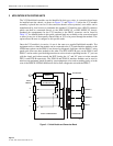
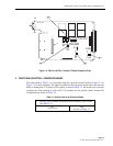
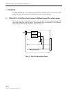
Working at the back of the equipment bay, install an FFM-01 or FFM-02 conversion board, as
appropriate, into a slot at the right-most vacant position of the chassis. Conversion boards can
only be installed in positions 1 through 16. Proceed as follows. While facing the back of the
chassis, hold the conversion board in a vertical position with the 34-pin connectors towards
yourself and the 25-pin connectors away for you. Place the three 25-pin connectors into the
three 25-pin mating connectors on the chassis and press firmly into place. Tighten the two
mounting screws per connector to assure a good connection.
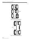
The FF-01 or FF-02 conversion board is meant to convert the 17th position of the RDC-01/PSC-
01 or RDC-02/PSC-02 PatchSwitch chassis to be used with the PSM-18 or PSM-19 interface
modules. In addition, this module can also convert position 1 to 16 of the RDC-01/PSC-01
chassis to be used as interface module positions. If position 1-16 of a RDC-02/PSC-02 chassis
must be converted to interface module positions, then the FF-02 must be used.
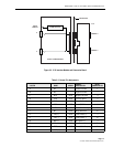
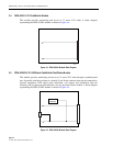
Bring the end of the DCE cable in from the side of the equipment rack and connect it to the
bottom connector on the conversion board. Form the cable neatly away from the board along an
equipment rack cable bracket towards the equipment rack upright. Be sure that the conversion
board does not have any side pressure from the cable in any direction. Using cable straps or
appropriate cord, fasten the cable to the cable bracket as applicable.
Bring the end of the “B” DTE cable in from the other side of the equipment rack and connect it
to the middle connector on the conversion board. Form the cable neatly away from the
connector sub-board along an equipment rack cable bracket towards the equipment rack upright.
Be sure that the conversion board does not have any side pressure from the cable in any
direction. Using cable straps or appropriate cord fasten the cable to the cable bracket. Bring the
end of the “A” DTE cable in from the the side of the equipment rack and connect it to the top
connector on the conversion board. Form the cable neatly away from the conversion board along
an equipment rack cable support bracket towards the equipment rack upright. Install additional
conversion boards using the directions above. Work from the right side of the chassis towards
the left (as seen from the rear). This gives room to the left in which to work and makes for a
much neater installation.
Carefully install the PatchSwitch V.35 module into the chassis making sure that the 96-pin DIN
connector on the front of the unit engages the connector in the chassis. Tighten the hold-down
screws on the front of the module
Plug the power transformer removed earlier back into its socket or turn on the power supply to
re-establish power for the units.