


ADCP-50-304 • Issue 19 • June 1999 • Section 2: Functional Description
Page 2-11
© 1999, ADC Telecommunications, Inc.
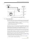
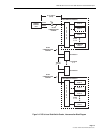
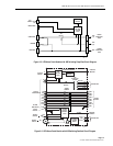
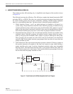
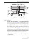
3.3 Patch Module with A/B Switching and In-Line Patch Access (PSM-02)
This PS module operates similarly to the PSM-01 by providing patching, switching, and switch
status indication, except it does not contain LED status indicators and alarm circuitry. A detailed
circuit diagram of this module is shown in Figure 2-7.
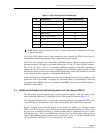
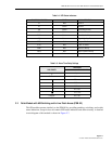
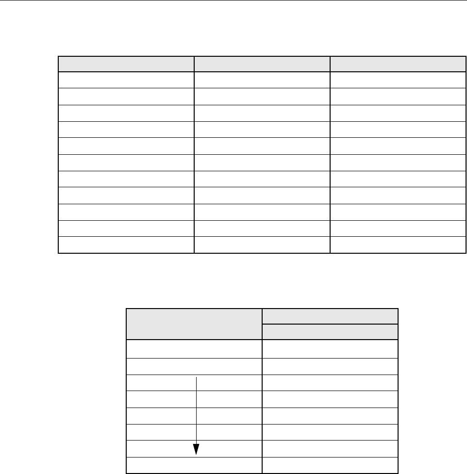
Table 2-4. LED Status Indicators
LED STATUS INDICATOR COLOR SIGNAL DEFINITION
A Red DTE-A
B Green DTE-B
TD Green Transmitted Data
RD Green Received Data
DCD Green Data Carrier Detect
SQ Green Signal Quality Detect
RTS Red Request To Send
CTS Red Clear To Send
DSR Red Data Set Ready
DTR Red Data Terminal Ready
ALM Yellow Alarm On
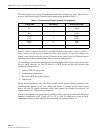
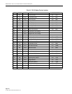
Table 2-5. Alarm Time Delay Settings
TIME DELAY
ARC LENGTH 50 HZ AND 60 HZ ENVIRONMENT
γ
1 µsec
Shortest 64 msec
256 msec
0.51 sec
1.02 sec
8.19 sec
32.75 sec
Longest 65.5 sec