


ADCP-50-304 • Issue 19 • June 1999 • Section 2: Functional Description
Page 2-7
© 1999, ADC Telecommunications, Inc.
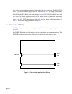
Up to four (4) PS chassis can be bank switched by daisy chaining the CMs via the 9-pin D-
subminiature and ensuring that each CM is strapped for dc pulse control.
The CM is also equipped with a selectable Autofallback feature. When an alarm condition is
detected, automatic switching is performed between the “A” and “B” sides of the PS modules.
The “A” to “B” side, or “B” to “A” automatic switching operation is selected by installing a
jumper on the CM circuit board. After configuring the Autofallback option, the PS module
detecting the alarm switches to the designated side (depending on the strap installed), it remains
in the switched position regardless of subsequent alarm status.
Alarm indications are automatically reset after the module detecting the alarm switches to the
appropriate side if the module is strapped for “Automatic Reset” (recommended). When the
front panel alarm (
ALM
) selection is positioned in the
OFF
position, the autofallback feature is
disabled for that module.
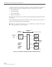
3.2 LED/Alarm Patch Module with A/B Switching and In-Line Patch Access (PSM-01)
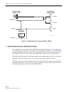
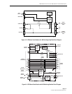
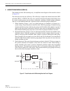
This PS module provides patching and switching functions together with lead status, switch
status, and alarm indications. A simplified circuit of this module is shown in Figure 2-5.
The A/B switch activates relays to connect the computer patch cord jack either the DTE-A port
or the DTE-B port. The indicators show A/B switch position, alarm and RS-232 lead status.
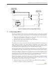
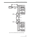
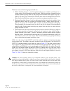
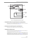
Figure 2-6 shows a more detailed diagram of the module. In addition to switching between
DTE-A or DTE-B, the relays also switch in the interlock jumper. Interlocking is used to protect
the user from accidentally switching a common backup piece of equipment onto two or more
different data lines. This is accomplished by allowing only the first module in that group to
switch. The remaining modules remain in the “normal state” or the “A” position. Modules in the
“B” position once switched to “A” will remain in the “A” position.
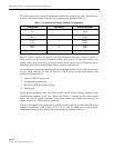
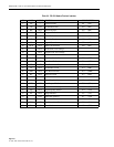
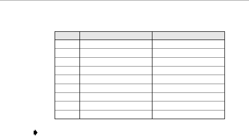
Table 2-2. DB-9 Pinout and Signal Characteristics
PIN OULTAGE INPUT CHANNEL (SWITCHED TO)
1 Chassis Ground N/A
2 –48V +5% (–5V min) B
3+5V +5% B
4 Remote Ground In B
5 Signal Return N/A
6 –48V +5% (–5V min) A
75V +5% A
8 Remote Ground In A
9 Signal Return N/A
Note:
The dc voltages indicated in Table 2-2 must be present for a minimum of 250 msec
to ensure switching.