


ADCP-50-304 • Issue 19 • June 1999 • Section 7: Operation
Page 7-18
© 1999, ADC Telecommunications, Inc.
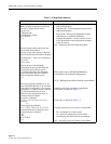
6.20 SPKxx Format
When a remote control device selects a PS chassis by issuing a “SPKxx” command, and then
requests status by issuing a “UP#” command, the CM responds with the condensed status
format. The condensed status format is a string of eight hexadecimal digits representing the
switch positions and alarm conditions for all 16 module slots contained in the selected PS
chassis. The “SPKxx” command is used by the RCU.
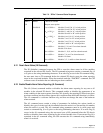
Each digit displayed is a hexadecimal code representing the switch position or alarm condition
for four PS modules. As shown in the example of Table 7-6, the first four hexadecimal digits
“56A3” define the switch positions for all l6 modules. The first hexadecimal digit “5” is
decoded to it’s binary equivalent which is “0101”. These four binary digits (bits) are assigned to
module addresses 15 (most significant) through 12. The response is read from left to right with
Module l5 assigned to the most significant bit in the hexadecimal code. A “0” bit indicates the
module is in the ‘A’ switch position and conversely, a “1” bit indicates the module is in the “B”
switch position.
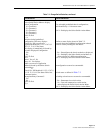
The second, third and fourth hexadecimal digits (616, A16 and 316) are decoded to their binary
equivalents which are “0110”, “1010”, and “00l1”, respectively. These 12 bits are assigned to
module addresses 11 through 0 (least significant). In this example (56A3)16, modules 15, 13,
11, 8 6, 4, 3, and 2 are in the “A” switch position and modules 14, l2, 10, 9, 7, 5, l, and 0 are in
the “B” switch position.
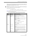
The alarm status for the same l6 PS modules is displayed in the last four hexadecimal digits
“10l0”. The alarm status code is read in the same manner as the switch status code. The fifth
hexadecimal digit “1” is decoded to it's binary equivalent which is “000l”. These four binary
digits (bits) are assigned to module addresses 15 (most significant) through 12. A “0” bit
indicates a no alarm condition for the module and conversely, a “l” bit indicates the module
detected an alarm.
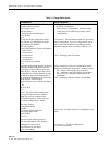
The second, third and fourth hexadecimal digits (0
16
, 1
16
and 0
16
) are decoded to their binary
equivalents which are “0000”, “000l”, and “0000”, respectively. These twelve bits are assigned
to module addresses l l through 0 (least significant). Therefore, in this example (1010)
16
,
modules l2 and 4 indicate an alarm condition is detected and the remaining modules indicate no
alarm is detected.
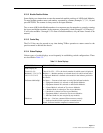
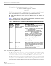
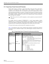
Table 7-6 shows an example of the condensed status format received by a terminal when a
request for status is issued for PS Chassis 0l. This format is primarily used by the Control
Module to transmit status to the ADC Remote Control Unit (PSR-03) indicator display.