


ADCP-50-304 • Issue 19 • June 1999 • Section 4: PatchSwitch X.21
Page 4-5
© 1999, ADC Telecommunications, Inc.
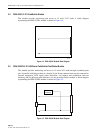
2.6 PSO-839001 Backplane Adapter Module
Three 15-pin D-sub connectors, located on the back of this backplane adapter provide a point of
connection for customer cabling. The top two rear connectors are female and the bottom one is
male. Three male 25 pin D-sub connectors on the front of the backplane adapter provide
connections to the RDC-01/PSC-01 PatchSwitch chassis backplane.
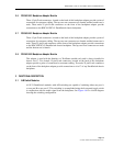
2.7 PSO-836001 Backplane Adapter Module
Three 15 pin D-sub connectors, located on the back of this backplane adapter provide a point of
connection for customer cabling. The top two rear connectors are female and the bottom one is
male. Three 25 pin D-sub connectors on the front of the backplane adapter provide connections
to the RDC-02/PSC-02 PatchSwitch chassis backplane. The top two front connectors are male
and the bottom one is female.
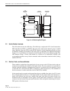
2.8 PSO-839002 Backplane Adapter Module
This adapter is used with the Interface or Test/Status module only and is always installed in
chassis slot 17. Two female 15-pin D-sub connectors, located on the back of this backplane
adapter provide a point of connection for customer cabling. Two male 25 pin D-sub connectors
on the front of the backplane adapter provide connections to slot 17 of any PatchSwitch chassis
backplane.
3 FUNCTIONAL DESCRIPTION
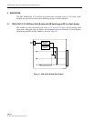
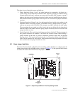
3.1 A/B Switch Modules
All X.21 PatchSwitch modules with A/B switching are capable of switching either rear port A
or rear port B to rear port C. This switching is accomplished using the front panel toggle switch
in conjunction with an enable signal from the backplane. See Figure 4-6 for a block diagram
showing the switching configuration.