


ADCP-50-304 • Issue 19 • June 1999 • Section 4: PatchSwitch X.21
Page 4-10
© 1999, ADC Telecommunications, Inc.
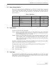
5 SPECIFICATIONS
Module specification are shown in Table 4-5.
6 INSTALLATION
Remove power to the shelf by turning off the power supply or unplugging the power supply
connected to the PatchSwitch chassis.
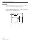
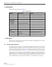
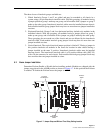
6.1 Interlock Jumper Installation
If an interlock option is desired for the system, the proper jumper must be connected in each A/B
Switch Module before installation in the chassis. Each A/B switch module has five interlock
positions. One jumper position for each of four interlock groups labeled 1 through 4 and one
vertical interlock group labeled V. See Figure 4-7 for the location of the jumpers on the module.
Interlocking is used to protect the user from accidentally switching a common backup piece of
equipment onto two or more different data lines. This is accomplished by allowing only the first
module in that group to switch. The remaining modules remain in the “normal state” or the “A”
position. Modules in the “B” position once switched to “A” will remain in the “A” position.
Table 4-5. Specifications
PARAMETER SPECIFICATIONS REMARKS
Dimensions
H
×
W
×
D 6.95
×
0.94
×
9.82 inches Install in RDC-01 or RDC-02 chassis
X.21 Modules 6.95
×
0.6
×
2.75 inches Install in RDC-01 or RDC-02 chassis
Adapter Mofule
Environmental
Temperature
Operating +32
°
to 122
°
F (0
°
to 50
°
C)
Storage –32
°
to 158
°
F (–40
°
to 70
°
C)
Relative humidity
Operating 10 to 80% No condensation
Storage 5 to 90% No condensation
Power
Power Supply +5 volts dc PSW-000003 (ac power source)
+12 volts dc
Current Supply 200.0 ma max.