


ADCP-50-304 • Issue 19 • June 1999 • Section 1: Introduction
Page 1-7
© 1999, ADC Telecommunications, Inc.
2.2.3 Data Converter Module (PSR-06)
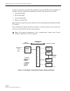
This module is a printed circuit board assembly with components, a front panel with four LED
status indicators and a rear 96-pin DIN connector. The module interfaces with the ADC Remote
Control Unit, a user's CRT terminal, or computer, and converts signals providing RS-422/RS-
232 compatibility to permit remote serial control for PatchSwitch equipment to be connected to
RS-232 modem or CRTs.
2.2.4 LED/Alarm Patch Module with A/B Switching (PSM-01)
This PS module is a printed circuit board assembly with components, a front panel (two toggle,
one rotary and one touch switch, three patch 26-pin connectors, and 11 LEDs), and rear 96-pin
DIN connector. It may be mounted in any of the first 16 module positions.
2.2.5 Patch Module with A/B Switching (PSM-02)
This PS module has the same features as PSM-01 except without RS-232/V.24 lead status
indicators and alarming.
2.2.6 A/B Switching Module (PSM-03)
This PS module is a printed circuit board assembly with components, a front panel (one toggle
switch and two LEDs) and a rear 96-pin DIN connector. It may be mounted in any of the first 16
module positions.
2.2.7 Led/Alarm Patch Module with A/B Switching and Off-Line Access (PSM-04)
This module is the same as PSM-01 except that when it is in A or B state, the off-line port
provides direct test access to the off-line device.
2.2.8 Patch Module with A/B Switching and Off-Line Access (PSM-05)
Same as PSM-04 except this module has no LEDs or alarm.
2.2.9 LED/Alarm Patch Interface (PSM-07)
This module (normally mounted in the 17th position of the chassis but may be mounted in the
1st through 16th position) is a patch interface module with LED and alarm; the model is a
printed circuit board assembly with components, a front panel (one toggle, one rotary and one
touch switch, two patch 26-pin connectors and nine LEDs), and a rear 96-pin DIN connector.
2.2.10 Patch Interface (PSM-08)
This module (normally mounted in the 17th position of the chassis but may be mounted in the
1st through 16th position) is a patch interface module; the module is a printed circuit board
assembly with a front panel (two patch 26-pin connectors) and rear 96-pin connector.