


ADCP-50-304 • Issue 19 • June 1999 • Section 2: Functional Description
Page 2-2
© 1999, ADC Telecommunications, Inc.
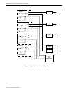
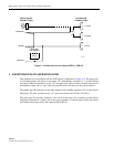
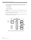
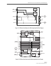
Figure 2-1. PatchSwitch with In-Line Access (PSM-01, PSM-02)
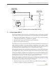
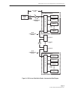
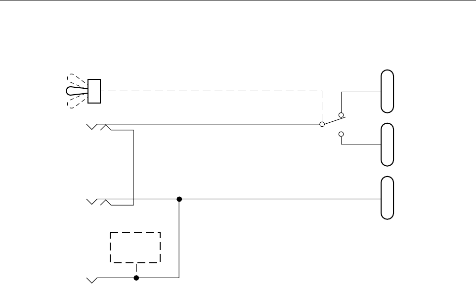
3 A/B SWITCHING WITH OFF-LINE MONITOR ACCESS
The capability for accessing the off-line DTE device is illustrated in Figure 2-2. The upper port
(A) provides patch cord access to the upper “D” subminiature connector (J-1) on the chassis
rear panel. When the module is in the “A” or normal state, this provides a monitor function. If
the module is in the “B” or “sub” state, this provides direct test access to the off-line device.
The middle port (B) functions in the same manner for the middle connector (J-2) on the chassis
backplane; “B” state, monitor access. “A” state, test access to the off-line “B” device.
The lower port (C) provides “intrusive” test access to the lower (J-3) connector on the chassis
backplane. Insertion of a patch cord in this port, regardless of switch status, breaks the circuit
and connects the patch cord to the common (DCE) device.
A
B
COMPUTER
J1 DTE-A
J2 DTE-B
J3 DCE
MODEM
MONITOR
LED/ALARM
ELECTRONICS
(PSM-01
ONLY)
FRONT PANEL
CONNECTIONS
BACKPLANE
CONNECTIONS
1607-A